Compression mount for window coverings

a technology for mounting brackets and window coverings, which is applied in the direction of machine supports, curtain suspension devices, door/window protective devices, etc., can solve the problems of insufficient installation of mounting brackets, relatively high level of skill and moderately complex mounting hardware, etc., and achieves convenient execution, reliable performance, and convenient manufacturing

Active Publication Date: 2008-01-17
SHADES UNLTD
View PDF63 Cites 4 Cited by
  • Summary
  • Abstract
  • Description
  • Claims
  • Application Information

AI Technical Summary

Benefits of technology

[0018] Another object of the present invention is to provide a method for mounting window coverings which is easy to execute and reliably holds the window covering in the desired position.
[0019] Another object of the present invention is to provide a mounting assembly which is readily manufacturable from commonly available materials and which can exhibit reliable performance.

Problems solved by technology

Such mounting has heretofore been generally difficult to achieve requiring a relatively high level of skill and moderately complex mounting hardware.
Installation of the mounting brackets is sufficiently difficult that many home owners choose to utilize window covering installation professionals, rather than performing the installation themselves.
Some attempts to avoid the requirement of installing mounting brackets or similar hardware have only achieved limited success.
Such mounting is generally only effective for particularly lightweight window coverings.
While Barettella is somewhat effective, the Barettella assembly must necessarily limit compression mounting forces to forces which can be readily exerted by the user installing the window covering.
Also, the Barettella window shade roller assembly is not readily adapted to facilitating resizing of a length of the window shade roller assembly to fit the particular width of the window in which the window shade is to be mounted.
The Barettella assembly is not modular and readily attachable / detachable from the rest of the shade.

Method used


Image

  • Compression mount for window coverings
  • Compression mount for window coverings
  • Compression mount for window coverings

Examples


Embodiment Construction

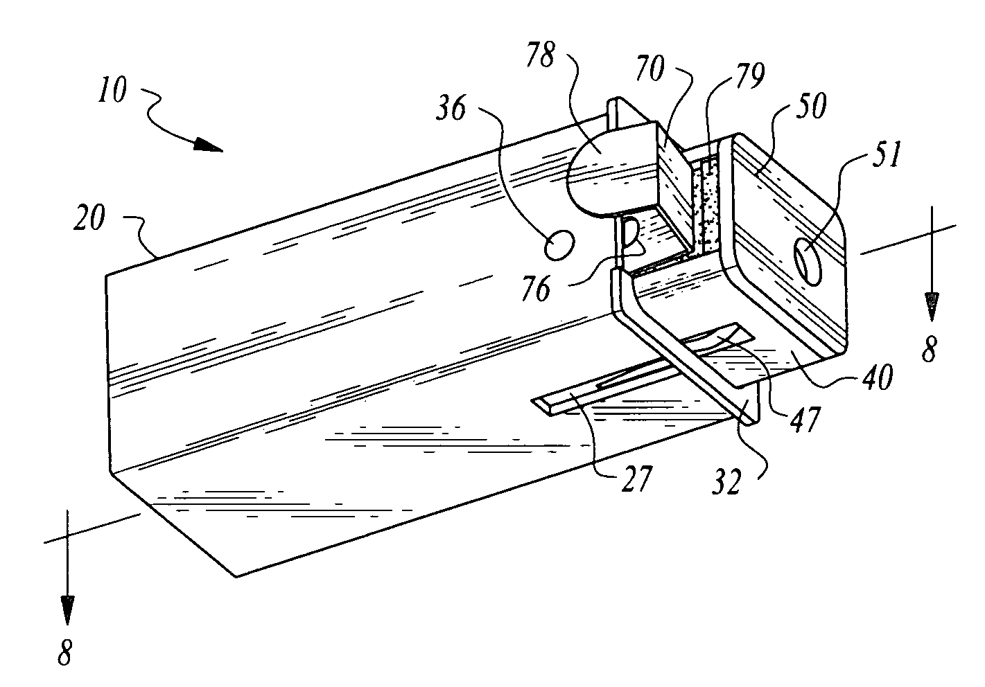
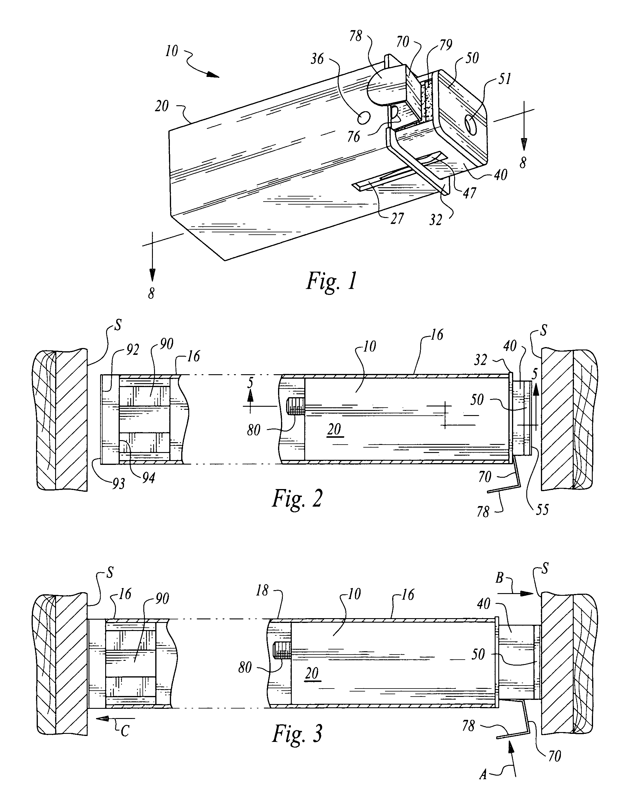
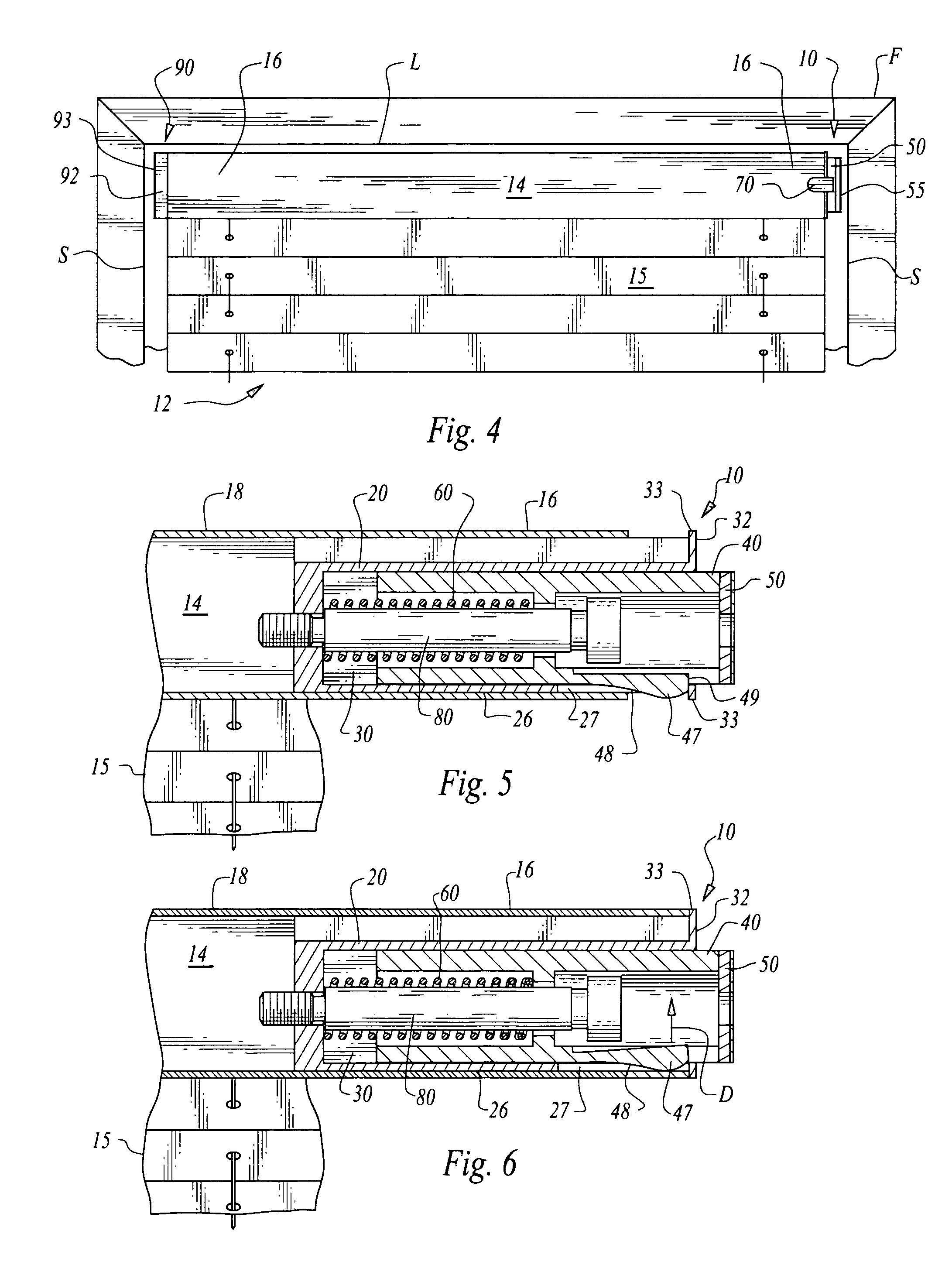
[0048] Referring to the drawings, wherein like reference numerals represent like parts throughout the various drawing figures, reference numeral 10 is directed to a compression mount assembly (FIG. 1) according to a preferred embodiment, for holding a shade 12 or other window covering adjacent a window frame F (FIG. 4). The compression mount assembly 10 fits within at least one end 16 of a top rail 14 of the shade 12. When the compression mount assembly 10 is activated, a slide 40 extends linearly out of the compression mount assembly 10 to abut a vertical side S of the window frame F with sufficient force to hold the entire shade 12 through the top rail 14 to the window frame F. Thus, no attachment hardware need be installed into the window frame F for mounting the shade 12 or other window covering adjacent the window frame F.

[0049] In essence, and with particular reference to FIG. 1, basic details of the preferred embodiment of the compression mount assembly 10 are described. The...


PUM


Abstract

A compression mount assembly is provided for securing a window covering to a window frame by compression forces between vertical sides of the window frame on opposite sides of the window. A housing is coupled to the window covering and a slide translates linearly within a cavity in the housing away from the housing to abut the side of the window frame. A driver, such as a spring, is located between the slide and the housing to urge the slide away from the housing. A trigger is optionally provided which holds the slide adjacent the housing, until the trigger is activated by pushing a button to release the slide from the housing and allow the slide to translate away from the housing. A fixed end cap is provided for an end of the window covering opposite the compression mount assembly and for abutting against an opposite side of the window frame.

Description

CROSS-REFERENCE TO RELATED APPLICATIONS [0001] This application is a continuation-in-part of U.S. patent application Ser. No. 10 / 966,279, filed on Oct. 15, 2004. FIELD OF THE INVENTION [0002] The following invention relates to mounting assemblies for mounting window coverings to a window frame surrounding a window. More particularly, this invention relates to window covering mounting assemblies and methods which rely upon compression forces exerted laterally away from ends of the window coverings against vertical sides of the window frame, and associated friction forces, to keep the window covering in place. BACKGROUND OF THE INVENTION [0003] Window coverings of various different configurations are provided to control the amount of light passing through a window, to selectively allow or preclude viewing through the window, and generally to decorate the window. Often windows are surrounded by a frame including a horizontal lintel above vertically oriented sides. It is often desirable...

Claims


Application Information

Patent Timeline
Patent Type & Authority Applications(United States)
IPC IPC(8): A47H1/14
CPCE06B9/323E06B9/266
Inventor SHEVICK, BARRY
Owner SHADES UNLTD
Why Eureka
Try Eureka