
Liquid storage container

a liquid storage container and liquid technology, applied in printing and other directions, can solve problems such as the breakdown of the recording head, and achieve the effect of increasing the liquid capacity of the liquid storage container and increasing the liquid volum

Inactive Publication Date: 2008-01-17
SEIKO EPSON CORP
View PDF24 Cites 15 Cited by
  • Summary
  • Abstract
  • Description
  • Claims
  • Application Information

AI Technical Summary

Benefits of technology

[0010] As described above, there is a problem that when the amount of ink remaining in the ink storage chamber is reduced, the fluidity of the ink toward the ink outlet is reduced in the ink storage chamber and the air bubbles are sucked into the ink guide path. This problem more easily occurs when the area of the bottom surface of the ink storage chamber is increased. Therefore, there is a serious problem that as the capacity of the ink storage chamber is increased to satisfy the requirements for mass printing or the like, the amount of ink that is discarded without being used is increased.
[0127] Therefore, even when vibration or temperature variation is applied during transportation, the ink I contained in the ink storage chambers does not easily flow into the atmosphere communicating path 150 or into the air chambers, i.e., the ink trap chamber 340 and the connecting buffer chamber 350. Accordingly, air bubbles are prevented from being generated in the ink storage chambers or ink guide paths due to the flow of the contained ink I.

Problems solved by technology

If the ink-ejecting operation is performed when there is no more ink in the ink cartridge and no ink can be supplied, the recording head will break down.

Method used


Image

  • Liquid storage container
  • Liquid storage container
  • Liquid storage container

Examples


Embodiment Construction

[0044] A liquid storage container according to a preferred embodiment of the present invention will be described in detail below with reference to the drawings.

[0045] In the embodiment described below, an ink cartridge attached to an inkjet recording apparatus (printer), which is an example of a liquid ejection apparatus, will be explained as an example of a liquid storage container.

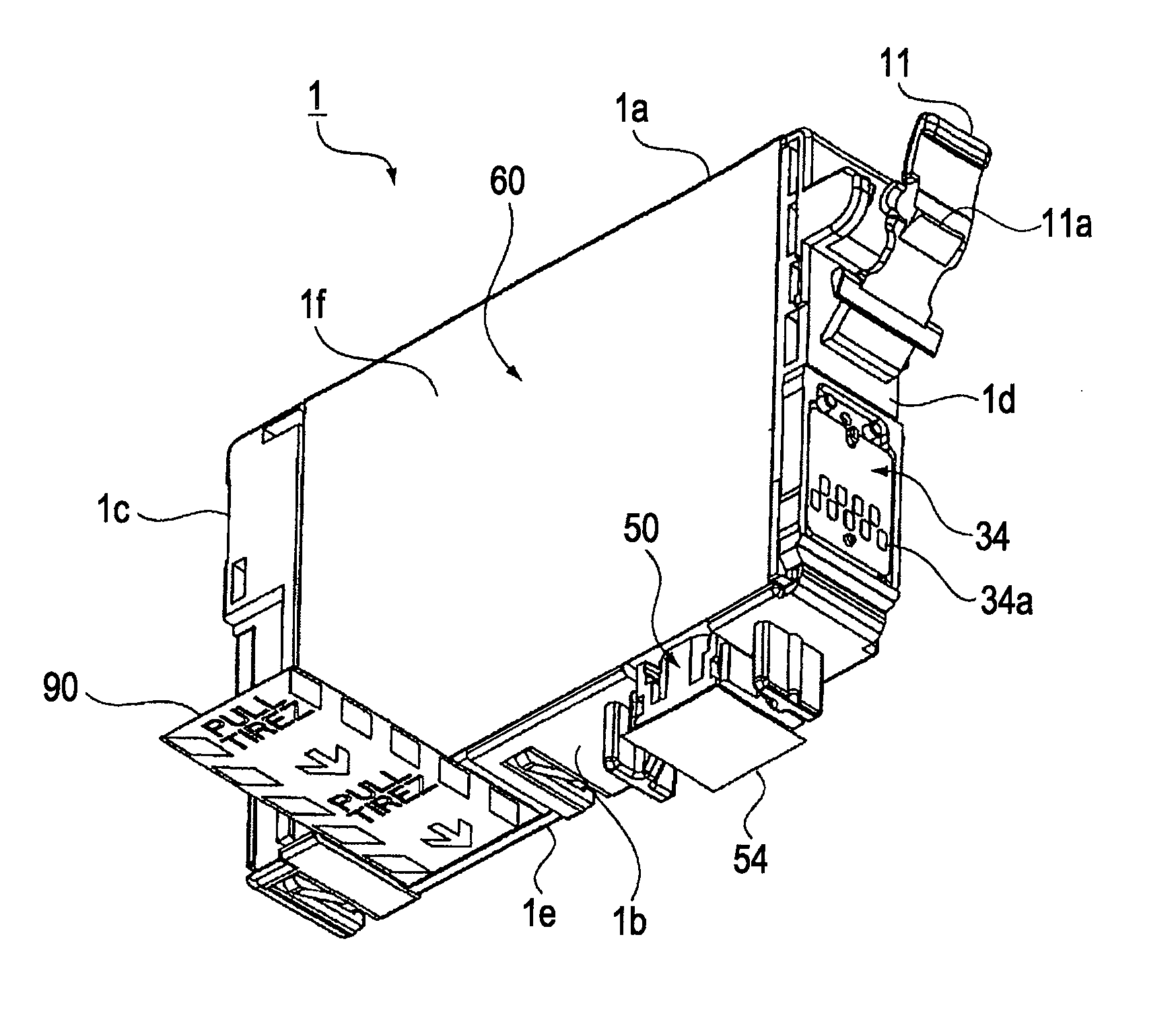
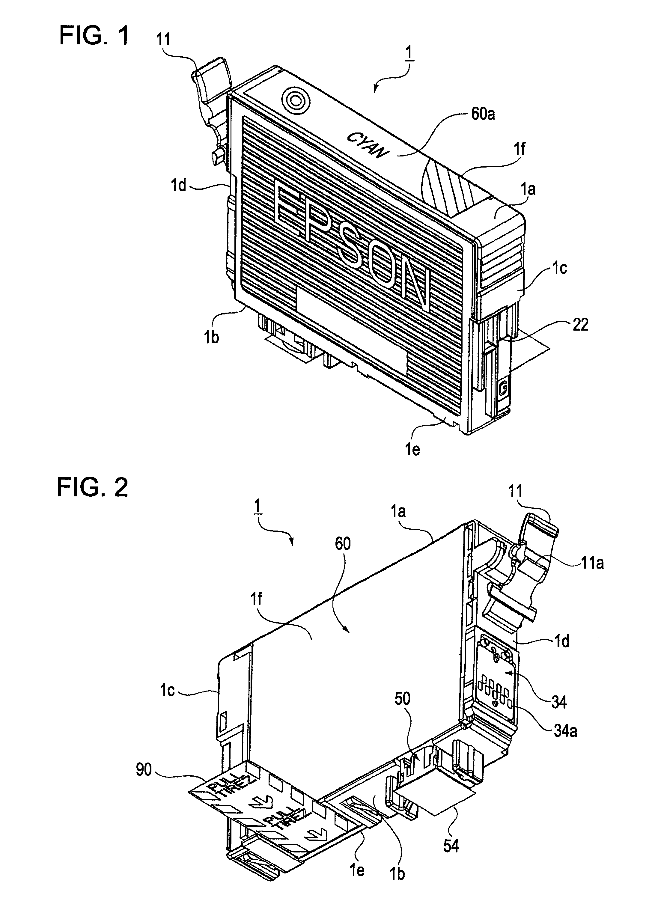
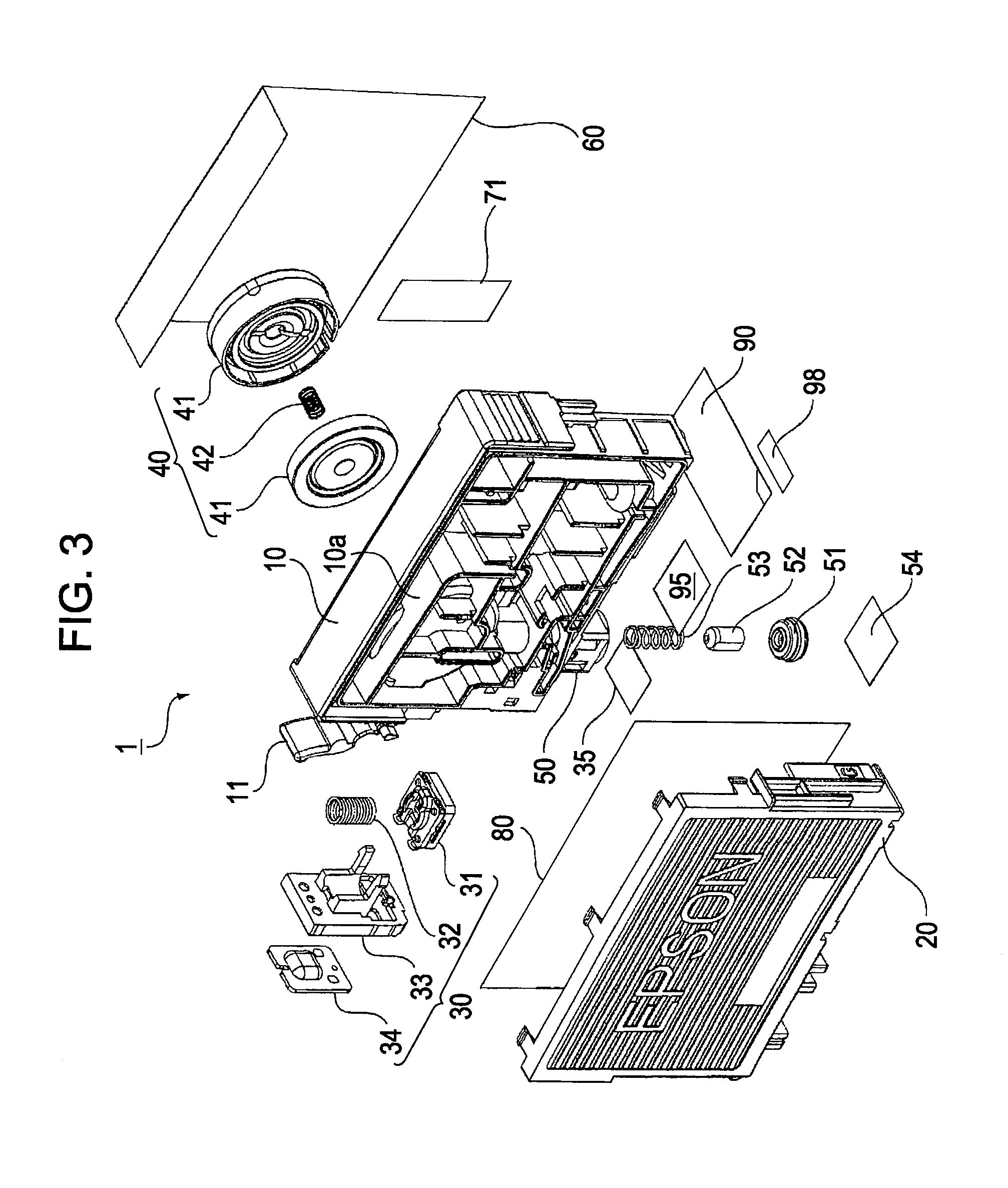
[0046]FIG. 1 is an external perspective view illustrating an ink cartridge as a liquid storage container according to an embodiment of the present invention. FIG. 2 is an external perspective view of the ink cartridge according to the present embodiment shown in FIG. 1 as viewed from the opposite angle. FIG. 3 is an exploded perspective view of the ink cartridge according to the present embodiment. FIG. 4 is an exploded perspective view of the ink cartridge according to the present embodiment shown in FIG. 3 as viewed from the opposite angle. FIG. 5 is a diagram illustrating the state in which the ink ...


PUM


Abstract

To provide a liquid storage container which can prevent a failure that air bubbles are sucked into a liquid guide path even when the amount of liquid remaining in the liquid storage chamber is reduced and which can considerably reduce the amount of liquid discarded without being used. [Solving Means] A liquid storage container 1 includes liquid storage chambers 370 and 430 from which liquid is guided to a liquid-supplying unit 50 through a liquid guide path and a liquid remaining-amount sensor 31 for detecting the presence / absence of the liquid on the basis of variation in residual vibration that occurs when air bubbles enter the liquid guide path. The liquid storage chambers 370 and 430 have concavities 374 and 434 in the bottom walls thereof. Liquid outlets 371 and 432 that communicate with the liquid guide path are formed at the bottom of the concavities 374 and 434, respectively. Therefore, air layers in the liquid storage chambers 370 and 430 are prevented from coming into contact with the liquid outlets 371 and 432, respectively, before the remaining liquid does.

Description

TECHNICAL FIELD [0001] The present invention relates to a liquid storage container having a container main body that is detachably attached to a liquid-consuming apparatus and supplying liquid contained in the container main body to the liquid-consuming apparatus. BACKGROUND ART [0002] An ink cartridge that contains liquid ink and an ink jet recording apparatus to which the ink cartridge is exchangeably attached are examples of the above-described liquid storage container and liquid-consuming apparatus, respectively. [0003] The ink cartridge generally has a container main body that is detachably attached to a cartridge-receiving unit of the ink jet recording apparatus. The container main body includes an ink storage chamber that is filled with ink, an ink-supplying hole for supplying the liquid contained in the ink storage chamber to the ink jet recording apparatus, an ink guide path through which the ink storage chamber and the ink-supplying hole communicate with each other, and an...

Claims


Application Information

Patent Timeline
IPC IPC(8): B41J2/175
CPCB41J2/17513B41J2002/17583B41J2/17566
Inventor ISHIZAWA, TAKUSHINADA, SATOSHI
Owner SEIKO EPSON CORP
Learn More