Vehicular lamp

a technology of vehicle lamps and lampshades, which is applied in the field of lamps, can solve the problems of increasing the cost of lamps, complicating the lamp structure, and not being able to emit light over a wide range of surface area

Inactive Publication Date: 2008-01-17
KOITO MFG CO LTD
View PDF3 Cites 108 Cited by
  • Summary
  • Abstract
  • Description
  • Claims
  • Application Information

AI Technical Summary

Benefits of technology

[0011] Accordingly, it is an object of the present invention to provide a vehicular lamp that provides a novel design in which the light-emitting area having a striped configuration is provided in a part of the lamp light-emitting surface.
[0012] It is another object of the present invention to provide a vehicular lamp that reduces the quantity of the light source, such as an LED, thus contributing lowering of the cost, size, and power consumption of the lamp.
[0013] It is still another object of the present invention to provide a vehicular lamp in which the amount of light emitted is prevented from being reduced by the light guide, thus increasing the use efficiency of the light.

Problems solved by technology

This is because the LED generally has a more narrow emission angular range compared to light bulbs and is therefore not suitable for emitting light over a wide range of surface area.
This in turn complicates the lamp structure and raises the costs of the lamps.
However, it is difficult to reduce the size of the lamp because the light bulb must be provided separately from the LED so that heat generated by the bulb does not affect the LED.
Furthermore, since light bulbs consume a large amount of power, it is not desirable to use them in terms of providing a lamp with low power consumption.
As a result, an excessively large number of LEDs are required to be installed in the lamp body, and it is difficult to realize lamps manufactured at a lower cost.
However, this is not the case for a lamp in which the light-emitting area with a striped configuration is provided in a part of the large light-emitting area.
This leads to a risk of losing desirable light distribution characteristics and of lowering the use efficiency of the light emitted by the LEDs.

Method used


Image

  • Vehicular lamp
  • Vehicular lamp
  • Vehicular lamp

Examples


Embodiment Construction

[0034] Embodiments of the present invention will be described below with reference to the accompanying drawings.

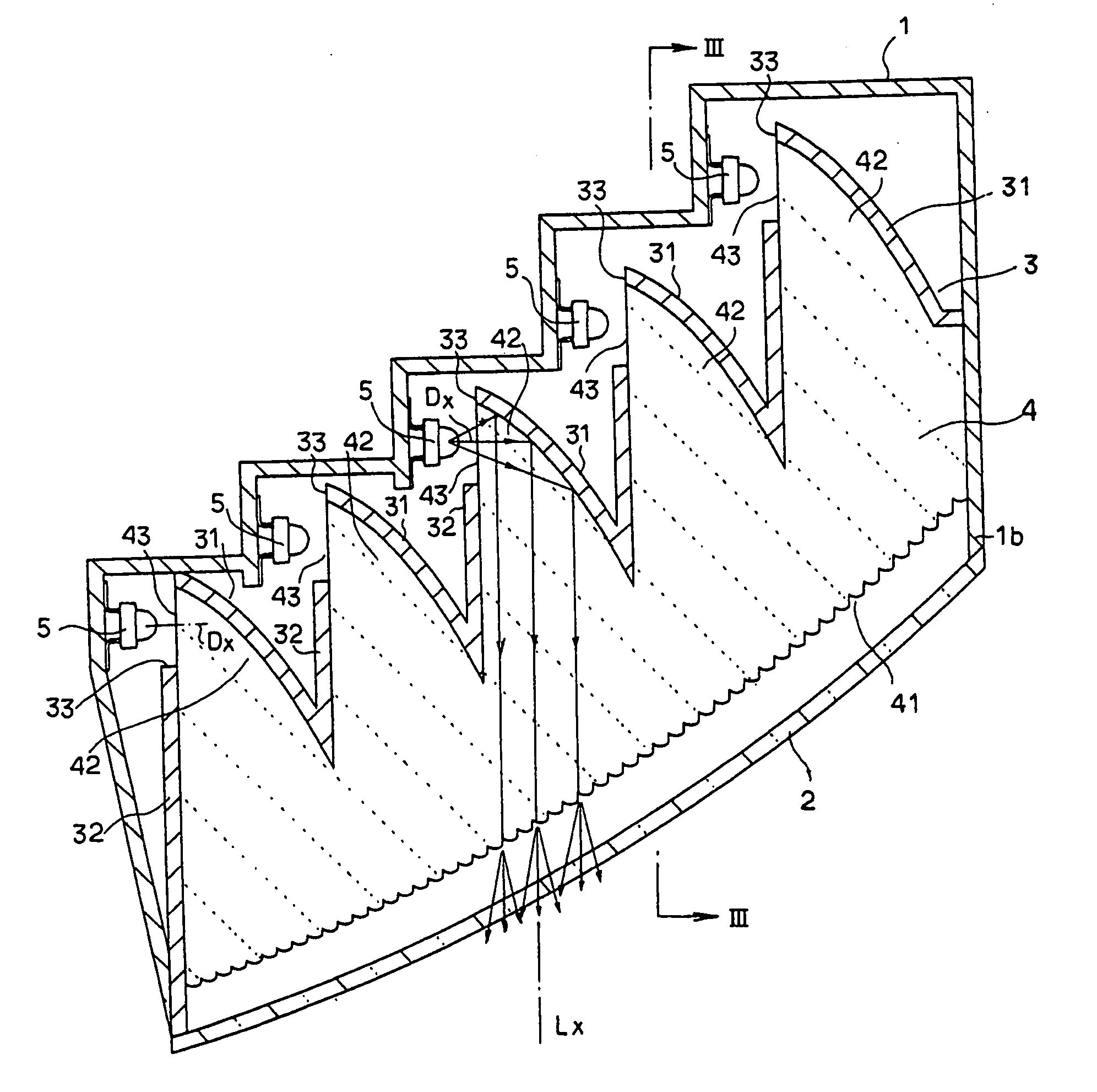
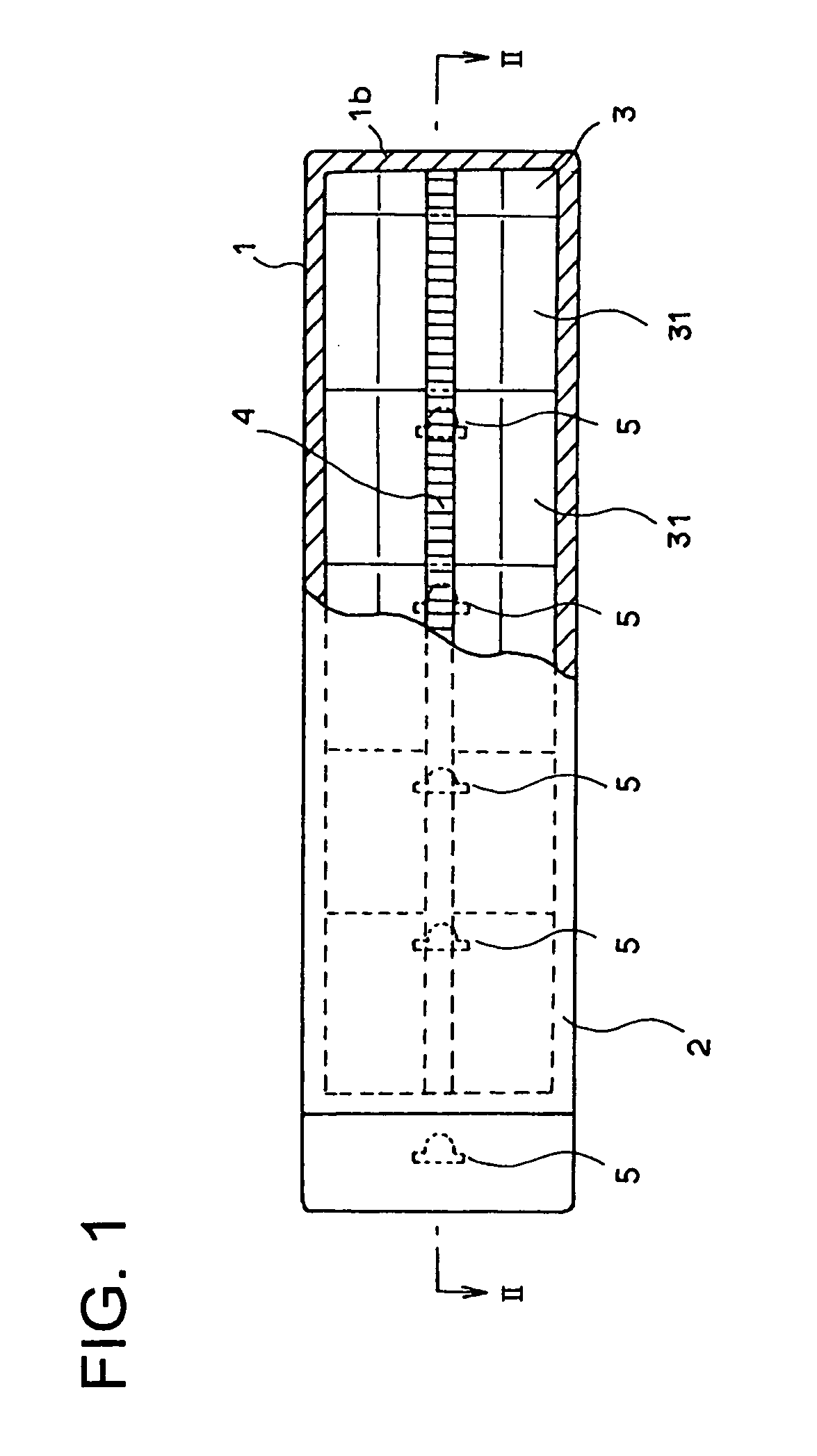
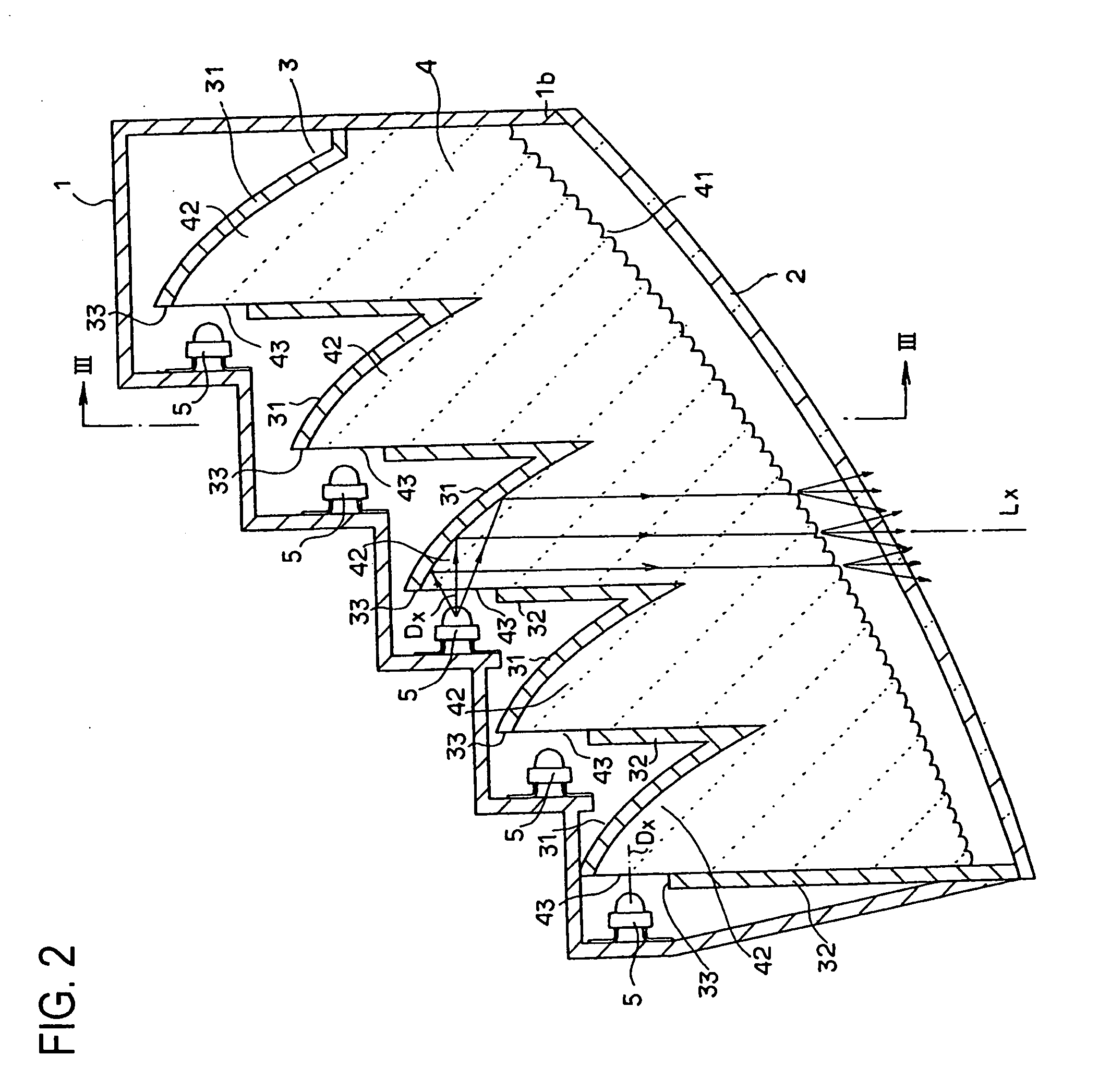
[0035]FIG. 1 is a front view of a part of the tail lamp of an automobile according to one embodiment of the present invention. FIG. 2 is a horizontal cross-sectional view of the lamp of FIG. 1, FIG. 3 is a vertical cross-sectional view of the structure shown in FIG. 2, and FIG. 4 is a disassembled perspective view of the lamp of FIG. 1. The tail lamp of the shown embodiment is a tail and stop lamp (T&SL) that combines the use of a stop lamp.

[0036] In FIGS. 1 through 4, an LED base 1, as best seen from FIG. 1, is formed in a horizontally oblong vessel configuration; and it comprises, as best seen from FIG. 4, a rear wall 1a, which is horizontally oblong as viewed from the front, and top, bottom, right, and left peripheral walls 1b.

[0037] The LED base 1 has a front opening 11 whose position in the lamp optical direction is inclined in the right-left direction (see FIG. 2)...


PUM

PropertyMeasurementUnit
thicknessaaaaaaaaaa
coloraaaaaaaaaa
light-emitting areaaaaaaaaaaa

Abstract

A vehicular lamp including an LED(s), a reflector having a reflective surface that reflects light from the LED(s) in the forward direction of the lamp, and a flat (plate-like) light guide(s) to which the light from the LED(s) is incident from one side of the light guide(s) and which radiates the light in the forward direction from another side. Light in the vicinity of the optical axis of the LED(s) is incident to the light guide(s), and other light is reflected by the reflective surface of the reflector, so that a part of light of the LED(s) is irradiated by the light guide(s), and other light is reflected and irradiated by the reflector, thus reducing the number of LEDs used and the size and power consumption of the lamp.

Description

BACKGROUND OF THE INVENTION [0001] 1. Field of the Invention [0002] The present invention relates to a lamp suitably used as a marker lamp in a vehicle such as an automobile and more particularly to a vehicular lamp having a striped light-emitting area on the light-emitting surface. [0003] 2. Description of the Related Art [0004] Various vehicular lamps that have novel light-emitting surfaces, especially marker lamps such as tail lamps and turn signal lamps, have been proposed in view of the demands to the design of vehicles. In one type of such a vehicular lamp, the light-emitting area with a striped configuration is defined on a part of the lamp light-emitting surface up to a plurality of locations, and such a striped area is designed so as to emit light with brightness, color, etc., different from other areas. [0005] For example, in the combination lamp disclosed in Japanese Patent Application Laid-Open (Kokai) No. 2006-49232, a plurality of lamps are disposed in the lamp body, a...

Claims


Application Information

Patent Timeline
Patent Type & Authority Applications(United States)
IPC IPC(8): F21V8/00F21V7/00F21W107/10
CPCB60Q1/2696F21V7/0091F21S43/14F21S43/239F21S43/243F21S43/249G02B6/0018G02B6/0031G02B6/0038G02B6/0068
Inventor KOIZUMI, HIROYANATSUME, KAZUNORI
Owner KOITO MFG CO LTD
Why Eureka
Try Eureka