Impact printhead

a printhead and impact technology, applied in the field of impact printheads, can solve the problems of high wear resistance materials, difficult to achieve prolonged life and low cost of impact printheads, wear of walls, etc., and achieve the effect of preventing higher order vibration of impact wires

Active Publication Date: 2008-01-17
OKI ELECTRIC IND CO LTD
View PDF2 Cites 14 Cited by
  • Summary
  • Abstract
  • Description
  • Claims
  • Application Information

AI Technical Summary

Benefits of technology

[0014]An object of the invention is to provide an impact printhead capable of pr

Problems solved by technology

Thus, repetitive impact operation of the impact wire 2 causes the impact wire 2 to repetitively beat the wall 15a, resulting in wear of the wall 15a.
Highly wear-

Method used


Image

  • Impact printhead
  • Impact printhead
  • Impact printhead

Examples


first embodiment

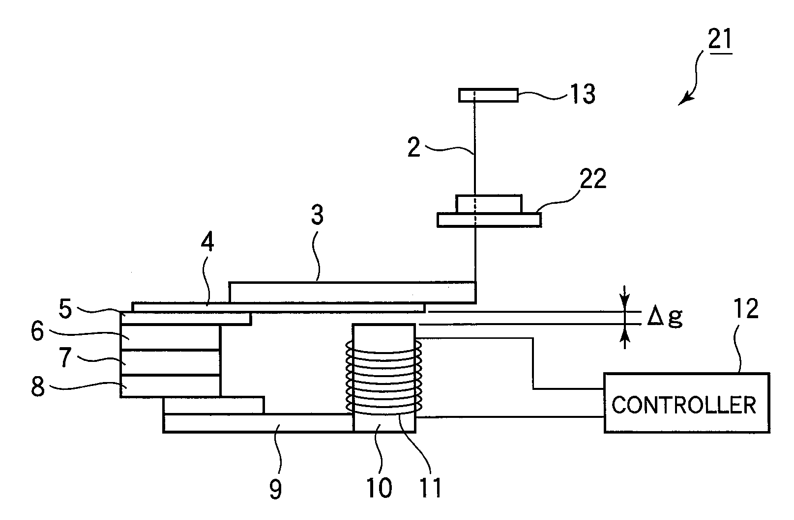
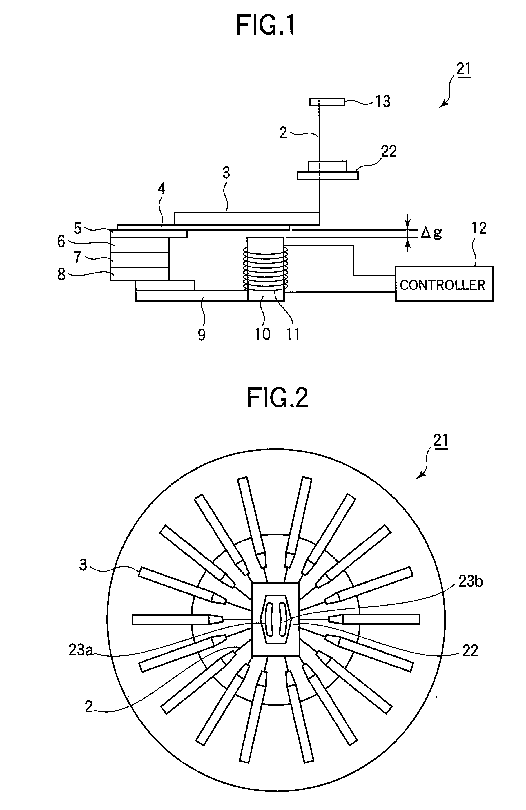
[0047]Referring to FIGS. 1 and 2, the impact printhead 21 includes a plurality of impact wires 2, secured to the end portion of an armature 3. FIG. 1 shows only one of the impact wires 2. The armature 3 is secured to a flat spring 4 such that the armature 3 and the flat spring 4 operate in unison. The base of the flat spring 4 is, for example, welded to a spacer 5 of a stacked structure of the spacer 5, a yoke 6, a permanent magnet 7, and a yoke 8.

[0048]A core 10 is mounted to a base yoke 9 located at the base portion of the impact printhead 21. A coil 11 is wound around the core 10. Current is applied to the coil 11 under control of a controller 12. The core 10 and the flat spring 4 are positioned relative to each other with a gap Δg between them. The impact wires 2 extend at their middle portion through a vibration restricting guide 22, and further extend through a wire guide 13 such that the free end potions of the impact wires 2 project through the wire guide 13 when the impact ...

second embodiment

[0063]FIG. 10 illustrates an impact printhead 31 of a second embodiment. FIG. 11 is a perspective view of a vibration restricting guide 32 of the second embodiment. The impact printhead 31 differs from the impact printhead 21 in that the vibration restricting guide 32 is used.

[0064]The vibration restricting guide 32 includes a base 32a and a projection 32b formed on an upper portion of the base 32a. The base 32a and the projection 32b are in one piece construction. As describe later, the projection 32b provides an additional wall surface through which the impact wire 2 contacts the vibration restricting guide 32. The hole 33 has a cross-section in the shape of an ellipse. The major axis of the ellipsoidal cross-section is in line with a line passing through the center “O” of the printhead 31. FIG. 12 is a front view illustrating the vibration restricting guide 32 as seen in a direction shown by arrow B.

[0065]The impact wire 2 tends to move toward the center “O” when the impact wire ...


PUM


Abstract

An impact printhead includes impact wires loosely held in a guide and driven to print. The printhead includes individual holes through which corresponding wires extend, and elongated holes formed in the guide for guiding the wires. The elongated hole includes a concave wall and a convex wall opposing each other. The wires are slidable on the convex wall. When the wires are not driven to print, the wires are at rest in pressure contact with the convex wall. Grooves may be formed in place of the elongated holes, and have second walls. The second wall lies substantially in a curved plane in which a first wall lies to define the individual hole. The wire is guided by the hole and groove. When the wire is not driven to print, the wire is at rest in pressure contact with the first and second walls.

Description

BACKGROUND OF THE INVENTION[0001]1. Field of the Invention[0002]The present invention relates to an impact printhead in which a plurality of impact wires are driven to print characters on a medium.[0003]2. Description of the Related Art[0004]A dot matrix printer or impact matrix printer employs a printhead that runs back and forth on the page and prints by impact, striking an ink-soaked cloth ribbon against the paper. Impact printers are capable of printing on a variety of media at low cost, and find their application in a variety of areas including an output device in an information processing system. Impact printheads may be of variety of types including a plunger type, a spring-charge type, and a clapper type.[0005]For an impact type printhead, impact wires are fixed to ends of armatures supported on one end of a cantilever type flat spring. A permanent magnet attracts the armature to a core such that mechanical energy is stored in the spring. When printing is performed, current ...

Claims


Application Information

Patent Timeline
IPC IPC(8): B41J2/265
CPCB41J2/265B41J2/25
Inventor KITABATAKE, TETSUYA
Owner OKI ELECTRIC IND CO LTD
Why Eureka
Try Eureka