Transverse Connector

a cross-connector and connector technology, applied in the field of cross-connector or connecting assembly, can solve the problems of cross-connectors with multiple points of articulation and multiple locking mechanisms that are difficult to implement in miss applications, and the number of obstacles is commonly encountered, so as to avoid the potential for cross-threading, avoid unwanted stress and physical damage to the rod, and minimize the effect of the connecting device and the actuator itsel

a cross-connector and connector technology, applied in the field of cross-connector or connecting assembly, can solve the problems of cross-connectors with multiple points of articulation and multiple locking mechanisms that are difficult to implement in miss applications, and the number of obstacles is commonly encountered, so as to avoid the potential for cross-threading, avoid unwanted stress and physical damage to the rod, and minimize the effect of the connecting device and the actuator itsel

US20080015588A1Active Publication Date: 2008-01-17XTANT MEDICAL HLDG INC

Image

  • Transverse Connector
  • Transverse Connector
  • Transverse Connector

Examples


Embodiment Construction

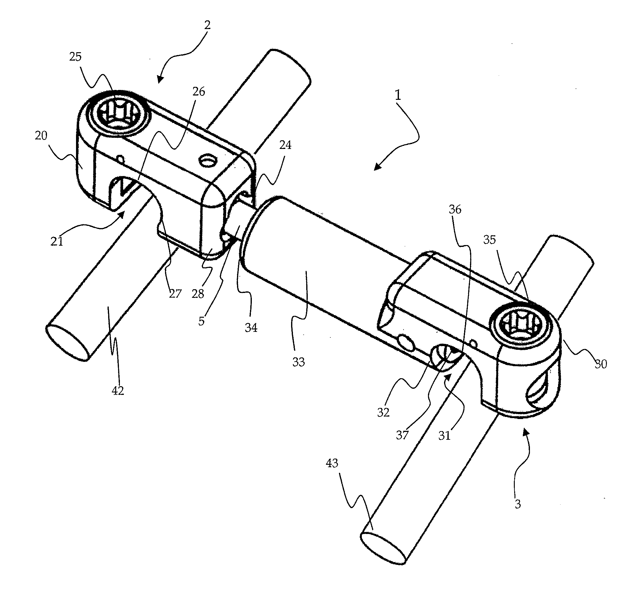
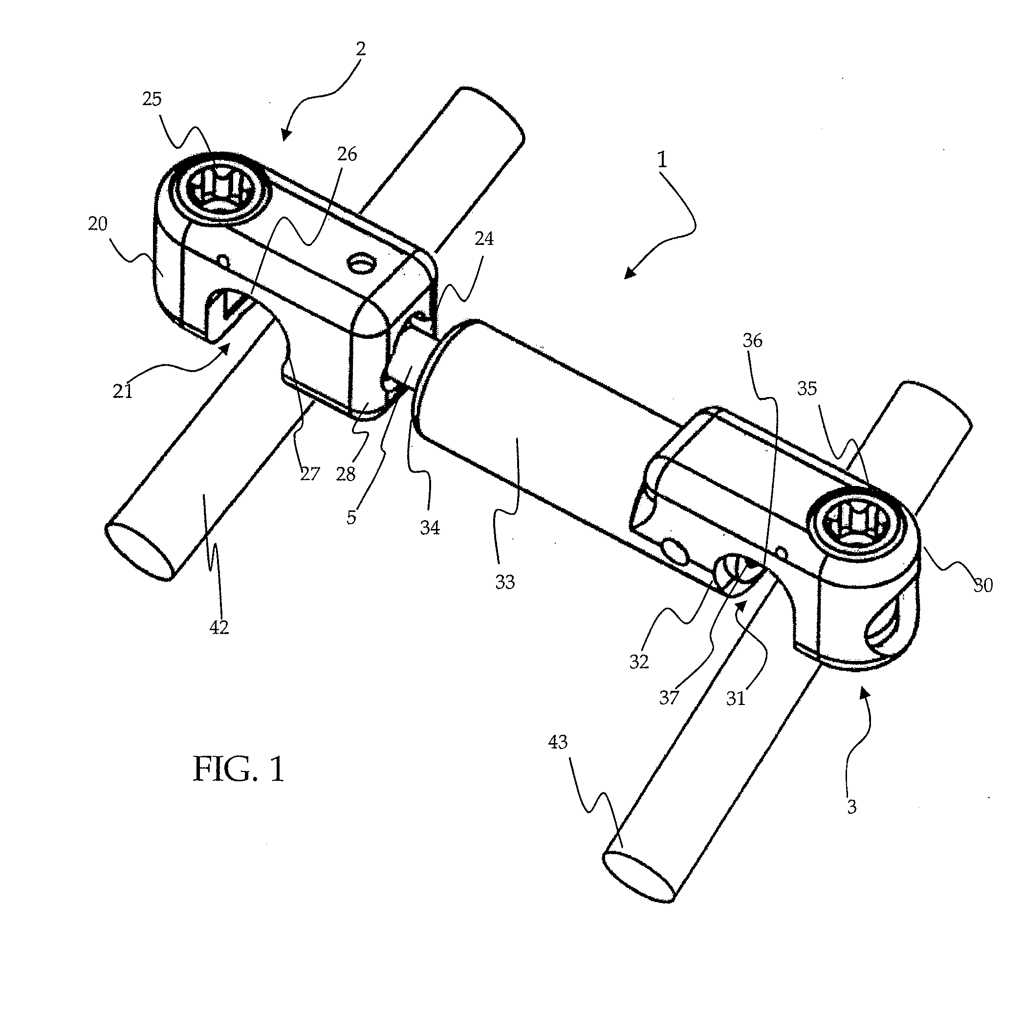
[0049]One embodiment of a transverse connecting assembly 1 for connecting two spinal rods 42 and 43 is shown in perspective by FIG. 1. The connecting assembly 1 comprises a first rod receiving device 2, a second rod receiving device 3, and a cross rod 5.

[0050]The first rod receiving device includes a rod receiving body 20 with a U-shaped recess 21 for receiving a spinal rod and a lateral opening 24 for receiving the cross rod 5. The recess 21 has an arcuate upper surface 26 and forms a seat configured to engage the surface of the spinal rod 42. A rotatable actuator 25 is disposed in the rod receiving body 20 adjacent to the recess 21. A side opening 24 in the side wall 28 of the body is sized so that the cross rod 5 may pivot. The opening 24 may be configured to permit pivoting of the cross rod 5 in one or more directions. Preferably, the cross rod 5 may pivot 360 degrees in the opening 24. In order to secure the first rod receiving device 2 to the spinal rod 42, the arcuate seat su...


PUM


Abstract

A crosslink or connecting assembly is provided to secure multiple spinal rods in relation to each other. The connecting assembly is disposed transversely between two spinal rods and has moveable components for rotating, pivoting, and extending portions of the connecting device in order to accommodate the positioning of the spinal rods.

Description

FIELD OF THE INVENTION[0001]The invention relates to a crosslink or connecting assembly and method to secure multiple spinal rods in relation to each other and, in particular, to a connecting assembly disposed transversely between two spinal rods that has moveable components for rotating, pivoting, and extending portions of the connecting device, as well as actuating members for locking the moveable components in place.BACKGROUND OF THE INVENTION[0002]In surgical procedures involving the spine, it is common to secure a pair of spinal rods to a series of vertebrae so that the rods are aligned essentially parallel to the spinal column. The spinal rods may serve to immobilize vertebrae, preventing unwanted flexion, extension, and rotation of vertebrae with respect to each other. It is often further desirable, or even necessary, to provide a connecting device to extend transversely between spinal rods, thereby securing the spinal rods relative to each other.[0003]Spinal rods are typical...

Claims


Application Information

Patent Timeline
17 Jan 2008
Publication
US20080015588A1
IPC
A61B17/58
CPC
A61B17/7052
Inventors
HAWKES, DAVID T.