Driving To Reduce Aging In An Active Matrix Led Display

a technology of led display and active matrix, which is applied in the direction of static indicating devices, instruments, electroluminescent light sources, etc., can solve the problems of prior art not being disclosed

Inactive Publication Date: 2008-01-24
KONINKLIJKE PHILIPS ELECTRONICS NV
View PDF9 Cites 16 Cited by
  • Summary
  • Abstract
  • Description
  • Claims
  • Application Information

AI Technical Summary

Benefits of technology

[0007] It is an object of the invention to provide a driver for an active matrix display in whic

Problems solved by technology

But, this prior art fails to disclose and to teach that the duty cycle of the faster aging pixels (which have a s

Method used


Image

  • Driving To Reduce Aging In An Active Matrix Led Display
  • Driving To Reduce Aging In An Active Matrix Led Display
  • Driving To Reduce Aging In An Active Matrix Led Display

Examples


Embodiment Construction

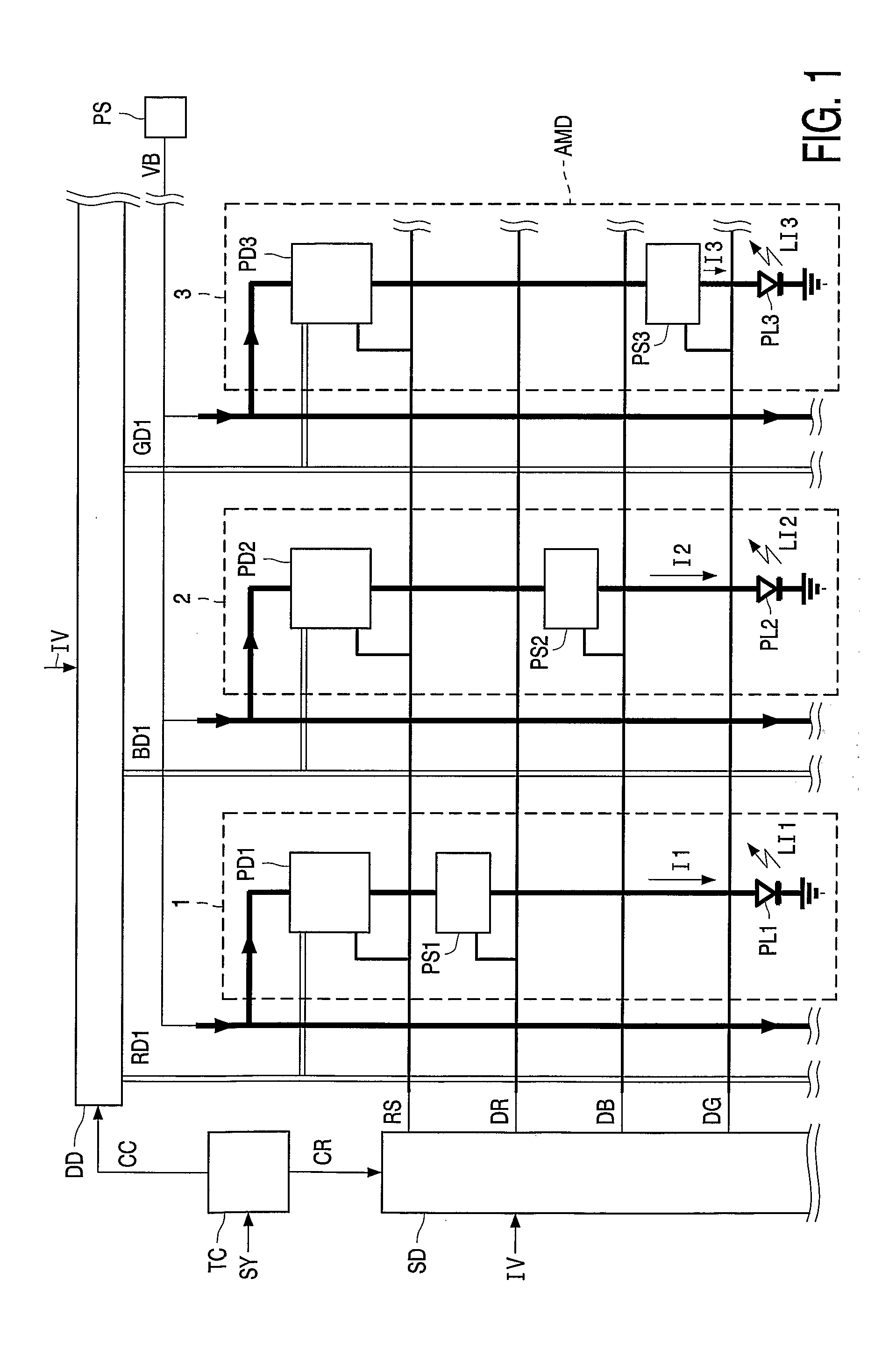
[0025]FIG. 1 shows a schematically view of an active matrix display apparatus. The active matrix display AMD shown only comprises three pixels 1, 2, and 3. In a practical embodiment, the matrix display comprises many more pixels.

[0026] Each pixel 1, 2, and 3 comprises a series arrangement of a pixel driving circuit PD1, PD2, and PD3 which are collectively referred to as PDi, a pixel switch circuit PS1, PS2, and PS3 which are collectively referred to as PSi, a light emitting element PL1, PL2, and PL3 which are collectively referred to as PLi and which emit light LI1, LI2, and LI3, respectively. Each one of the pixel driving circuits PDi comprises an input to receive a power supply voltage VB, an input to receive a data signal Di (RD1, BD1, and GD1, respectively for the pixels 1, 2, 3 shown), an input to receive a row select signal RS, and an output to supply a current to the associated pixel switch circuit PSi. The pixels 1, 2, 3 are collectively referred to as Pi.

[0027] Each one o...


PUM


Abstract

A driver (DD, SD, PD1, PS1, PD2, PS2) supplies, at a frame rate, a first current (I1) with a first duty cycle being smaller than one to a first light emitting element (PL1) of an active matrix display (AMD) and a second current (I2) to a second light emitting element (PL2) of the active matrix display (AMD). The second light emitting element (PL2) has a shorter lifetime than the first light emitting element (PL1). The driver (DD, SD, PD1, PS1, PD2, PS2) limits controls the second duty cycle to be larger than the first duty cycle.

Description

FIELD OF THE INVENTION [0001] The invention relates to a driver for an active matrix display, a display module comprising an active matrix display and such a driver, a display apparatus comprising the display module, and a method of driving an active matrix display. BACKGROUND OF THE INVENTION [0002] U.S. Pat. No. 6,583,775 B1 discloses an active matrix display of which the pixels comprise light emitting elements which have a brightness level depending on an amount of current supplied to the light emitting elements. The light emitting elements are OLED's (organic light emitting diodes). A scanning line drive circuit selects the rows of pixels one by one, each one during a row select period. A data line drive circuit supplies data signals in parallel to the row of selected pixels. The pixels comprise a pixel drive circuit which determines a level of the current dependent on the data received. At the start of a row select period, the light emitting elements start to emit with a bright...

Claims


Application Information

Patent Timeline
IPC IPC(8): G09G3/32
CPCG09G3/2011G09G3/2014G09G3/2081G09G3/3233G09G2320/043G09G2300/0819G09G2300/0852G09G2300/0861G09G2320/0261G09G3/3291G09G3/20G09G3/30G09G3/32H05B33/12
Inventor CORDES, CLAUS NICOBUDZELAAR, FRANKVOGELS, INGRID MARIA LAURENTIA CORNELIAHOPPENBROUWERS, JURGENKLOMPENHOUWER, MICHIEL ADRIAANSZOONVAN DER VAART, NIJS CORNELIS
Owner KONINKLIJKE PHILIPS ELECTRONICS NV
Why Eureka
Try Eureka