Print apparatus, print method and recording medium driving apparatus
a technology of printing apparatus and driving apparatus, which is applied in the direction of instruments, data recording, visual presentation, etc., can solve the problems of risk of a difference being produced in the print density, and achieve the effect of uniform print density and reducing the number of ink droplets ejected
- Summary
- Abstract
- Description
- Claims
- Application Information
AI Technical Summary
Benefits of technology
Problems solved by technology
Method used
Image
Examples
second embodiment
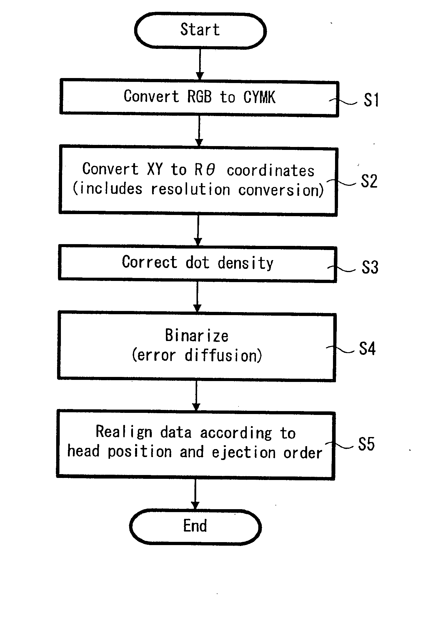
[0042] FIGS. 10 to 15 show a print apparatus according to the present invention. FIGS. 10A and 10B are diagrams useful in explaining the thinning of dots in the polar coordinate data, FIG. 11 is a diagram useful in explaining correction weightings, FIGS. 12, 13A, and 13B are diagrams useful in explaining an error diffusion method, FIGS. 14A to 14C are diagrams useful in explaining the process as far as the generation of ink ejection data, and FIGS. 15A to 15I are diagrams useful in explaining a calculation process of the error diffusion method.
[0043] FIGS. 16 to 21 show a third embodiment of a print apparatus according to the present invention. FIG. 16 is a plan view, FIG. 17 is a perspective view, FIG. 18 is a block diagram showing the flow of signals in the print apparatus shown in FIG. 16, FIG. 19 is a schematic diagram useful in explaining the print apparatus shown in FIG. 16, FIG. 20 is a diagram useful in explaining printing carried out with a constant angular velocity for the...
first embodiment
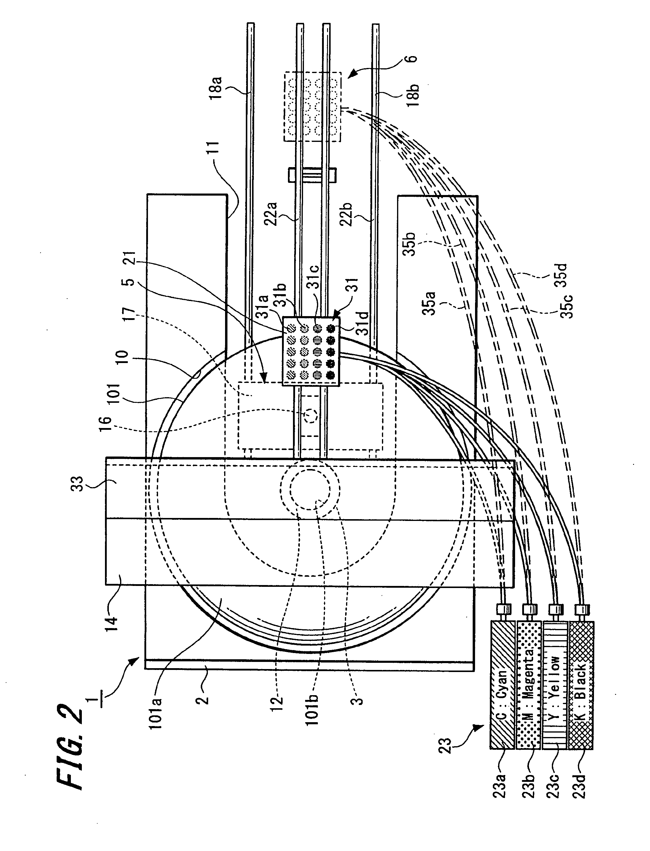
[0044]FIG. 2 and FIG. 3 show an optical disc apparatus 1 (recording medium driving apparatus) that is a print apparatus according to the present invention. The optical disc apparatus 1 is capable of recording (writing) a new information signal onto and / or reproducing (reading) an information signal that has been recorded in advance from an information recording surface (“recording surface”) of an optical disc 101, such as a CD-R or DVD-RW, as a specific example of a “printed object” and is also capable of printing visible information, such as characters and designs, on a label surface (main surface) 101a of the optical disc 101 that is a specific example of a “print surface”.
[0045] As shown in FIGS. 2 to 4, the optical disc apparatus 1 includes a tray 2 that conveys the optical disc 101, a spindle motor 3 that is a specific example of a “rotating unit” for rotating the optical disc 101 conveyed by the tray 2, a recording and / or reproducing unit 5 that writes and / or reads information...
third embodiment
[0195] Here, the radius rN+1 of the virtual dots dN+1 will be described. The radius rN+1 of the virtual dots dN+1 can be calculated as follows. In the same way as in the third embodiment, if the radius rN of the dots dN is 59.5 mm, the radius RN+1 of the dot dN+1 whose center coincides with the movement axis Q when such dot dN+1 has been moved in a direction perpendicular to the movement axis Q so that the center coincides with the standard axis O is approximately 58.6 mm. If the offset from the standard axis O to the movement axis Q is 15 mm, the radius rN+1 of the dots dN+1 is calculated according to the Pythagorean theorem at approximately 60.5 mm.
[0196] For example, when the dN−12 group is the dot di group to be weighted, as shown in Table 1 and Table 2 described above, the radius ri of the dots di is approximately 48.0 mm (rN−12). Also, the radius ri+1 of the dots di+1 is approximately 48.9 mm (rN−11) and the radius ri−1 of the dots di−1 is approximately 47.0 mm (rN−13).
[0197]...
PUM
 Abstract
Description
Claims
Application Information
 - R&D
- Intellectual Property
- Life Sciences
- Materials
- Tech Scout
- Unparalleled Data Quality
- Higher Quality Content
- 60% Fewer Hallucinations
Browse by: Latest US Patents, China's latest patents, Technical Efficacy Thesaurus, Application Domain, Technology Topic, Popular Technical Reports.
© 2025 PatSnap. All rights reserved.Legal|Privacy policy|Modern Slavery Act Transparency Statement|Sitemap|About US| Contact US: help@patsnap.com


