
Interference prediction apparatus, interference prediction method, and interference prediction program in computer-readable medium

a technology of interference prediction and computer-readable medium, which is applied in the direction of electrical equipment, radio transmission, transmission monitoring, etc., can solve the problems of channel interference becoming serious, throughput deterioration or communication failure, and many effort is needed to manually set the unused wireless channel or wireless channel

Inactive Publication Date: 2008-01-24
NEC COMM SYST
View PDF3 Cites 28 Cited by
  • Summary
  • Abstract
  • Description
  • Claims
  • Application Information

AI Technical Summary

Benefits of technology

The invention provides an apparatus, method, and program for predicting which wireless channel will be affected by interference. This is useful for identifying which channels should be avoided for wireless communication. The apparatus measures the strength of signals received from each channel and predicts which channel will be affected by interference based on these measurements. This helps to improve the efficiency of wireless communication by avoiding channels that are likely to interfere with each other.

Problems solved by technology

Accordingly, when a plurality of wireless apparatuses is used, a problem of channel interference becomes serious.
When the channel interference occurs, problems such as throughput deterioration or communication failure take place.
However, much effort is needed to manually set the unused wireless channel or wireless channel of which the occurrence rate of the channel interference is low.
Thus, even if a wireless channel in which no beacon is detected is set as a communication channel by applying the technique of document 1, channel interference may occur when a wireless channel is set as a new communication channel within a predetermined range of a neighboring wireless channel.
However, the technique of detecting the state of the propagation path of the frequency band in document 2, and the technique of extracting features of the spectrum pattern by comparing the spectrum pattern of the received wave with the typical spectrum pattern in document 3 are responsible for increasing costs of apparatuses.
For this reason, even if the technique of document 4 is applied to a wireless LAN, it is impossible to avoid an occurrence of channel interference unique to the wireless LAN.

Method used

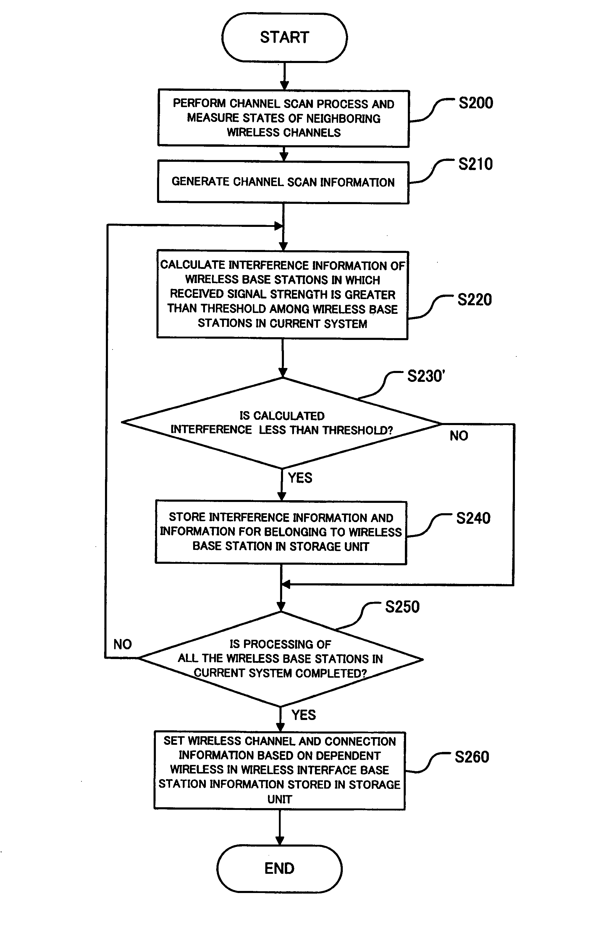

Image

  • Interference prediction apparatus, interference prediction method, and interference prediction program in computer-readable medium
  • Interference prediction apparatus, interference prediction method, and interference prediction program in computer-readable medium
  • Interference prediction apparatus, interference prediction method, and interference prediction program in computer-readable medium

Examples


first exemplary embodiment

[0056]

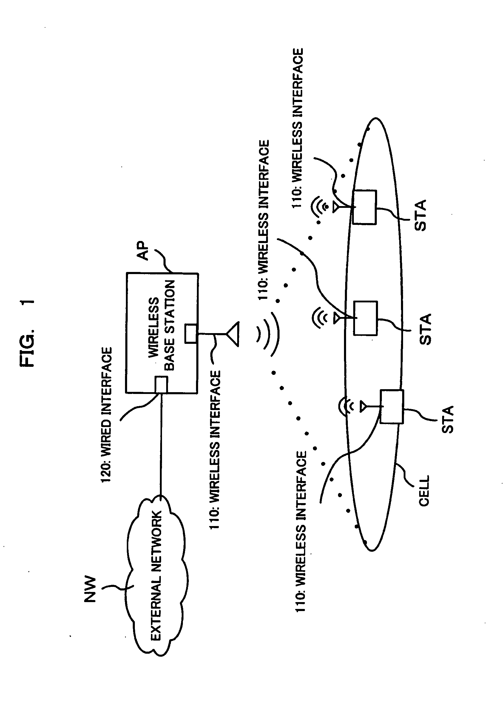
[0057] First, a system configuration of a wireless communication system will be described with reference to FIG. 1.

[0058] The wireless communication system includes a plurality of wireless terminal apparatuses STA and a wireless base station AP.

[0059] The wireless base station AP includes wired interfaces 120 used to access an external network NW and wireless interfaces 110 for accessing the wireless base station AP or wireless terminal apparatuses STA.

[0060] Each of wireless terminal apparatuses STA includes a wireless interface 110 used to access the wireless base station AP or another wireless terminal apparatus STA.

[0061]

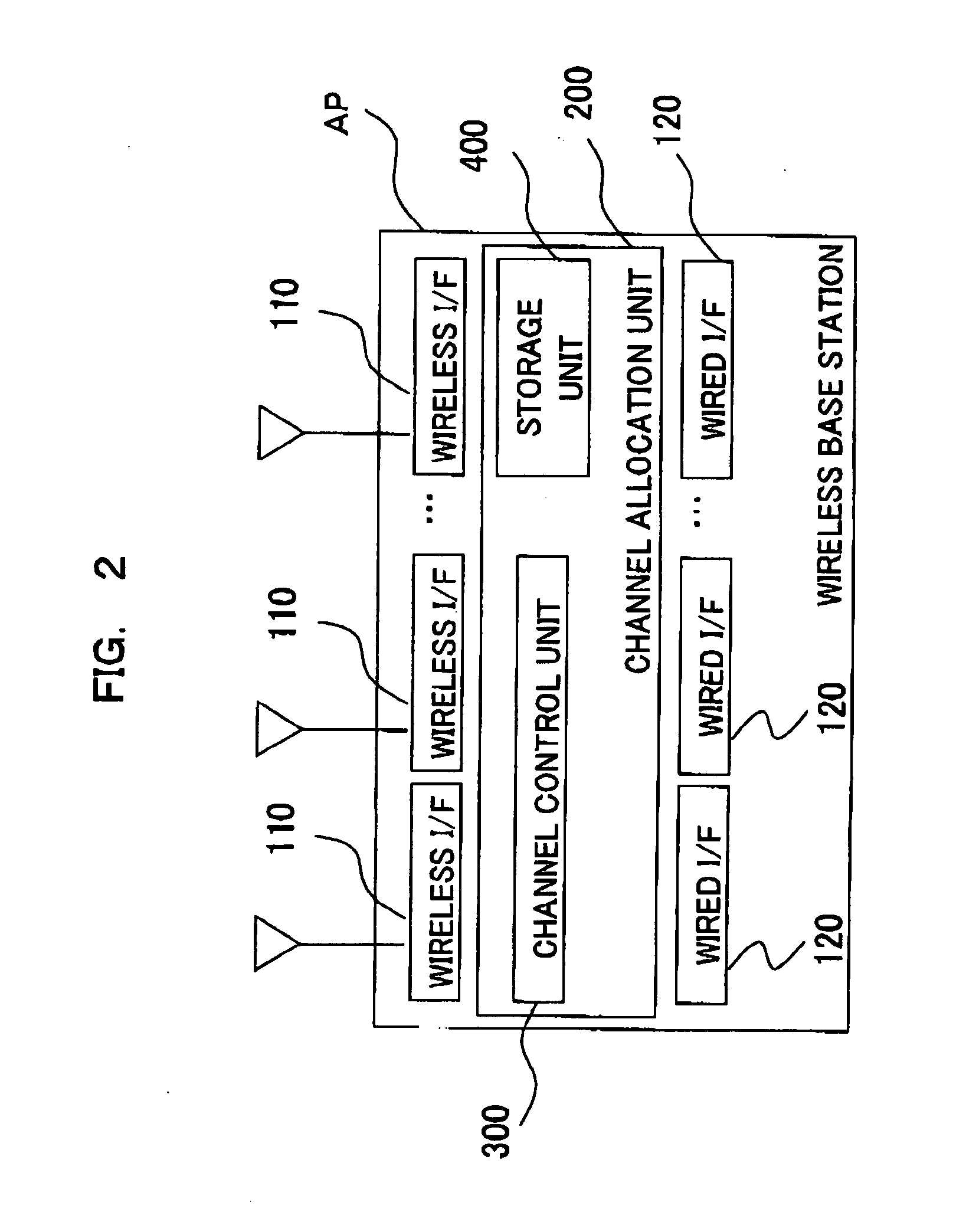
[0062] Next, an internal configuration of the wireless base station AP will be described with reference to FIG. 2.

[0063] As shown in FIG. 2, a wireless base station AP includes wireless interfaces 110, wired interfaces 120, and a channel allocation unit 200.

[0064] The wireless interfaces 110 are designed to perform wireless communication. The wireles...

second exemplary embodiment

[0150] Now, a second embodiment of the present invention will be described.

[0151] In the first exemplary embodiment, the wireless base station AP shown in FIG. 1 performs the series of processes shown in FIG. 5, selects a wireless channel in which channel interference does not occur on the basis of a received signal strength measured for each wireless channel and an interference area predicted for each wireless channel, and allocates the selected wireless channel as a wireless channel to be used for wireless communication.

[0152] In the second exemplary embodiment of the present invention, the wireless terminal apparatus STA shown in FIG. 1 selects a wireless base station AP in which channel interference does not occur on the basis of a received signal strength measured for each wireless channel and an interference channel predicted for each wireless channel, and accesses the selected wireless base station AP.

[0153] This configuration enables the wireless terminal apparatus STA to...

third exemplary embodiment

[0233] Now, a third exemplary embodiment of the present invention will be described.

[0234] In a wireless communication system, a wireless base station AP includes, as shown in FIG. 18, a location (position) information acquisition unit 500 capable of acquiring its own location (position) information.

[0235] This configuration enables the wireless base station AP to acquire its own location information and to adjust an interference area of a wireless channel in which channel interference occurs in consideration of its own location information.

[0236] Therefore, the wireless base station AP allocates a wireless channel in consideration of its own location information. Accordingly, it is possible to allocate a suitable wireless channel in which an occurrence rate of interference is low.

[0237] Hereinafter, the wireless communication will be described with reference to FIGS. 18 to 20.

[0238] First, an internal configuration of the wireless base station AP that constitutes the wireless ...


PUM


Abstract

An interference prediction apparatus capable of predicting a wireless channel in which channel interference occurs, measures a received signal strength for each wireless channel and predicts an interference area of the wireless channel in which channel interference occurs for each wireless channel on the basis of the received signal strength for each wireless channel.

Description

[0001] This application is based upon and claims the benefit of priority from Japanese patent application No. 2006-193105, filed on Jul. 13, 2006, the disclosure of which is incorporated herein in its entirety by reference. BACKGROUND OF THE INVENTION [0002] 1. Field of the Invention [0003] The present invention relates to an interference prediction apparatus, an interference prediction method, and an interference prediction program in a computer-readable medium capable of predicting an occurrence of channel interference. [0004] 2. Description of Related Art [0005] Recently, a wireless LAN has been rapidly distributed due to easy installation. A plurality of apparatuses is designed to wirelessly communicate with one another via the wireless LAN. [0006] When 2.4 GHz IEEE802.11b is applied, non-interfering (non-overlapping) wireless channels include, in 2.4 GHz wireless LAN, at most three channels (for example, 1ch, 6ch, and 11ch) in the USA. [0007] The maximum range of the wireless c...

Claims


Application Information

Patent Timeline
Patent Type & Authority Applications(United States)
IPC IPC(8): H04B7/216H04W72/54
CPCH04W72/082H04W72/541
Inventor MATSUMOTOITO, TETSUYA
Owner NEC COMM SYST
Learn More