
Computer implemented method for defining an input product

a technology of input products and implemented methods, which is applied in the field of computer programs and systems, can solve the problems of reducing the number of input products,

Active Publication Date: 2008-01-24
DASSAULT SYSTEMES
View PDF6 Cites 6 Cited by
  • Summary
  • Abstract
  • Description
  • Claims
  • Application Information

AI Technical Summary

Benefits of technology

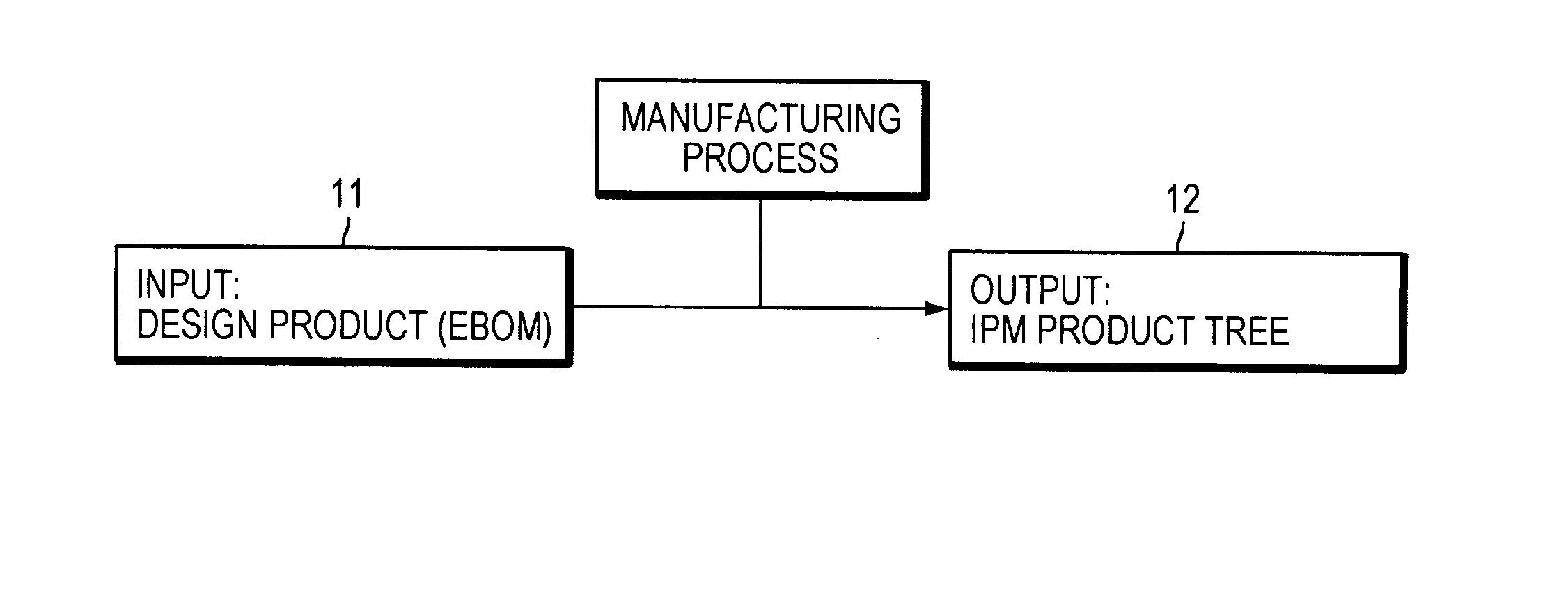
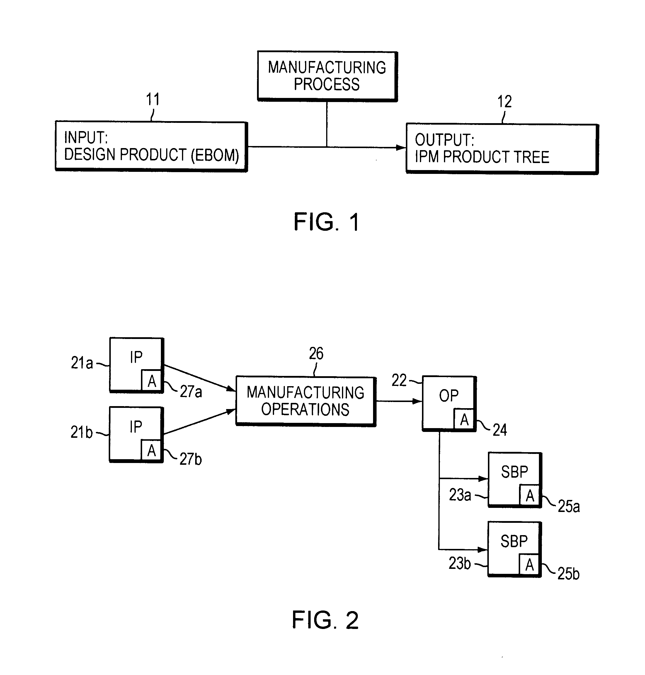
The invention proposes a system and method for defining an input product to be manufactured into an output product. The method involves receiving an output product with attributes and a sub-product with attributes, and associating a manufacturing operation with the output product based on the attributes of the output product. The method then derives the attributes of the input product from the attributes of the sub-product and the manufacturing operation. The invention also includes a computer executable program code and a computer assisted manufacturing process using the computer implemented method. The technical effects of the invention include improved efficiency in manufacturing and preparation operations, better utilization of manufacturing resources, and improved quality of the final product.

Problems solved by technology

However, in some industries such as shipbuilding for instance, manufacturing process is not a mere assembly of design input sub-products that can be pre-fabricated to exact dimensions and fit exactly with each other.
Also, heavy steel parts tend to shrink and distort whenever heated during welding operations, due to high temperature gradients.
For instance, workers will have to walk on a panel and may fall through cutouts during intermediate assembly stages.

Method used


Image

  • Computer implemented method for defining an input product
  • Computer implemented method for defining an input product
  • Computer implemented method for defining an input product

Examples


first example

DESCRIPTION OF FIRST EXAMPLE

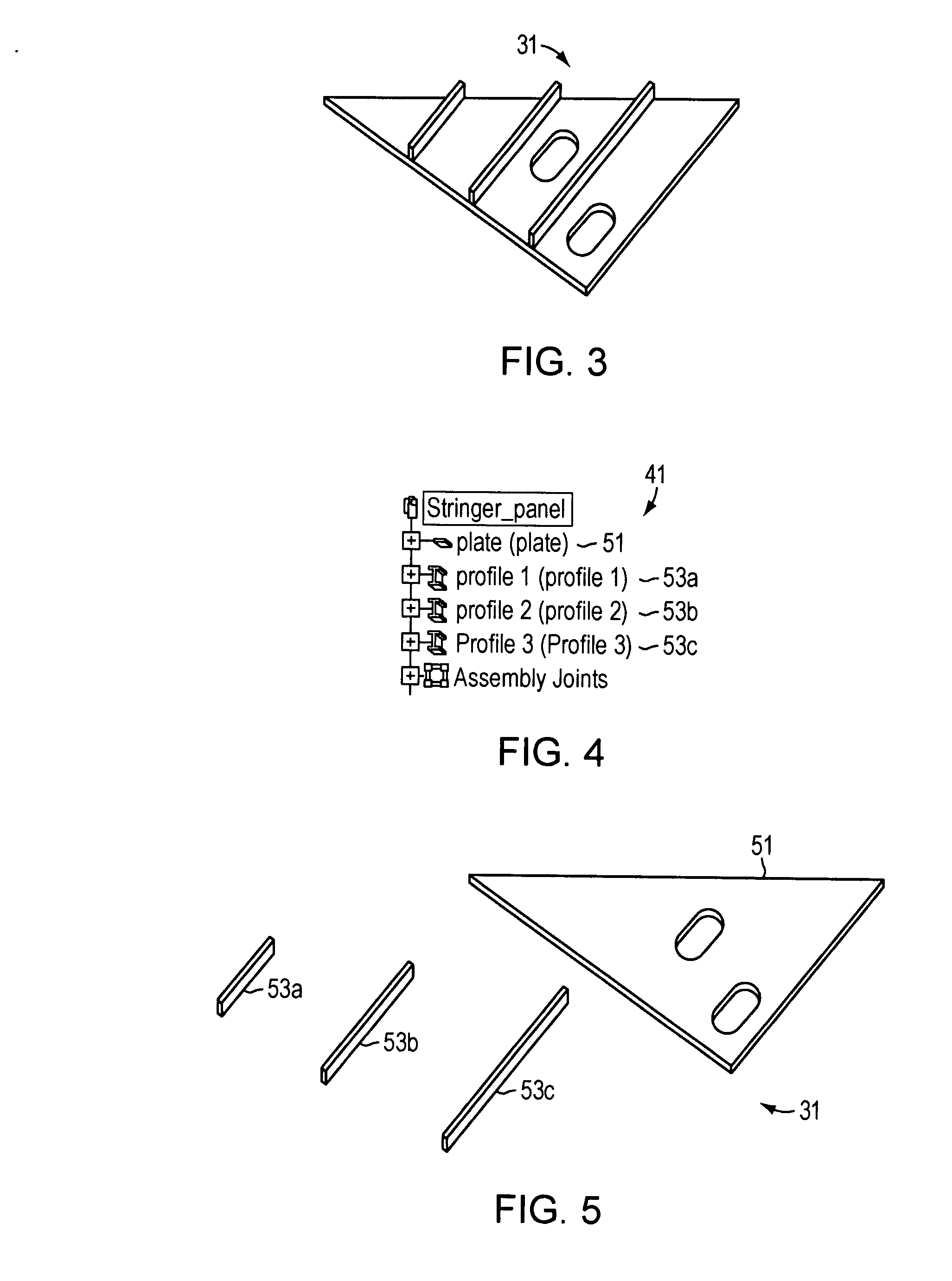
[0081] A first example will be described with reference to FIGS. 3 to 15 relating to a “stringer panel” as the output product 31, i.e. the target design product to be manufactured. The computer implemented method of the invention will define attributes of input products to be used for manufacturing said stringer panel output product 31.

[0082] Because the attributes of the input products are defined through a manufacturing process approach, the following description will first describe the manufacturing process to produce the stringer panel 31. Then, how every input product is defined, using a process-driven approach, will be described.

[0083]FIG. 3 shows a design view of a stringer panel product 31. This is the target design to be manufactured. It was designed, for instance, using structure design capabilities of CATIA. FIG. 4 shows its product structure tree 41 and FIG. 5 shows an exploded view of the sub-products 51,53 of the stringer panel assembly. A...

second example

DESCRIPTION OF SECOND EXAMPLE

[0142] A second example will be described with reference to FIGS. 16 to 21 relating to a “curved plate” as the output product 163. The computer implemented method of the invention will define attributes of an input product to be used for manufacturing said curved plate output product 163.

[0143]FIG. 16 shows a large curved shell panel 161, which consists of eight curved plates (such as at 163) and eight twisted profiles 162a, b, c, d, e, f, g, h to be assembled together during a so-called “curved panel assembly macro-activity”. Here again, this activity is performed in a dedicated manufacturing shop, with specialized resources.

[0144] However, in this example, we focus on one of the eight shell plates of the curved panel 161, as shown in FIG. 17, and we will consider the curved plate 163 with attachment lines shown in FIG. 18 as the output product to be manufactured. This curved plate output product comprises only one sub-product (the curved plate 163) a...


PUM


Abstract

A computer system and implemented method for defining an input product to be manufactured into an output product, comprises steps of: (a) receiving an output product having attributes and comprising at least one sub-product, said sub-product having attributes; (b) associating to said output product a manufacturing operation identified among a plurality of manufacturing operations; (c) defining attributes of said input product, said input product attributes deriving from modification of attributes of the at least one sub-product according to the associated manufacturing operation. The computer implemented method of the invention thus derives input products from the output product to be manufactured with a process oriented approach. Design modifications on output product can be directly and automatically taken into account in input products.

Description

RELATED APPLICATION [0001] This application claims priority under 35 U.S.C. § 119 or 365 to European Patent Application No. EP 06291187.0, filed Jul. 21, 2006. [0002] The entire teachings of the above application are incorporated herein by reference. FIELD OF THE INVENTION [0003] The invention relates to the field of computer programs and systems, and more specifically to a computer implemented method for defining specifications of an input product to be manufactured into an output product according to its manufacturing process. BACKGROUND OF THE INVENTION [0004] Computer-aided techniques include Computer-Aided Design or CAD, which relates to software solutions for authoring product design. Similarly, CAE is an acronym for Computer-Aided Engineering, e.g. it relates to software solutions for simulating the physical behavior of a future product. CAM stands for Computer-Aided Manufacturing and typically includes software solutions for defining manufacturing operations. [0005] A number...

Claims


Application Information

Patent Timeline
Patent Type & Authority Applications(United States)
IPC IPC(8): G06F19/00
CPCG05B19/41805G05B19/40937Y02P90/02G06Q50/04G06F30/13
Inventor THIBAUD, COLAS
Owner DASSAULT SYSTEMES
Learn More