Control of Driveline Geometry

a technology of driveline geometry and geometry, applied in the direction of vehicle position/course/altitude control, process and machine control, instruments, etc., can solve the problems of increased wear, unbalance in the system, and acceleration and deceleration of the end of the propeller shaft rotational acceleration and deceleration,

Inactive Publication Date: 2008-01-24
VOLVO LASTVAGNAR AB
View PDF11 Cites 8 Cited by
  • Summary
  • Abstract
  • Description
  • Claims
  • Application Information

AI Technical Summary

Problems solved by technology

The propeller shaft angles vary, e.g. when the vehicle is loaded, which may result in unbalances in the system whereby the ends of the propeller shaft rotationally accelerate and decelerate at different rates.
The resulting vibrations lead to noise, increased wear, and discomfort for the driver.

Method used


Image

  • Control of Driveline Geometry
  • Control of Driveline Geometry
  • Control of Driveline Geometry

Examples


Embodiment Construction

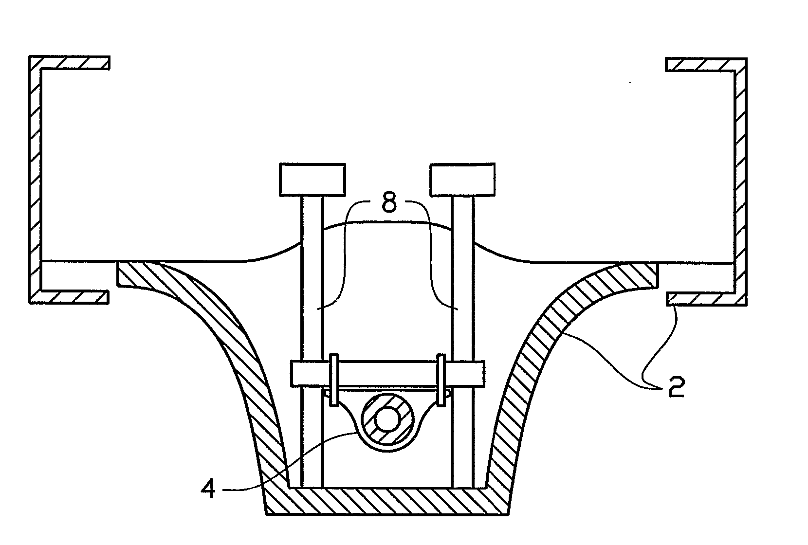
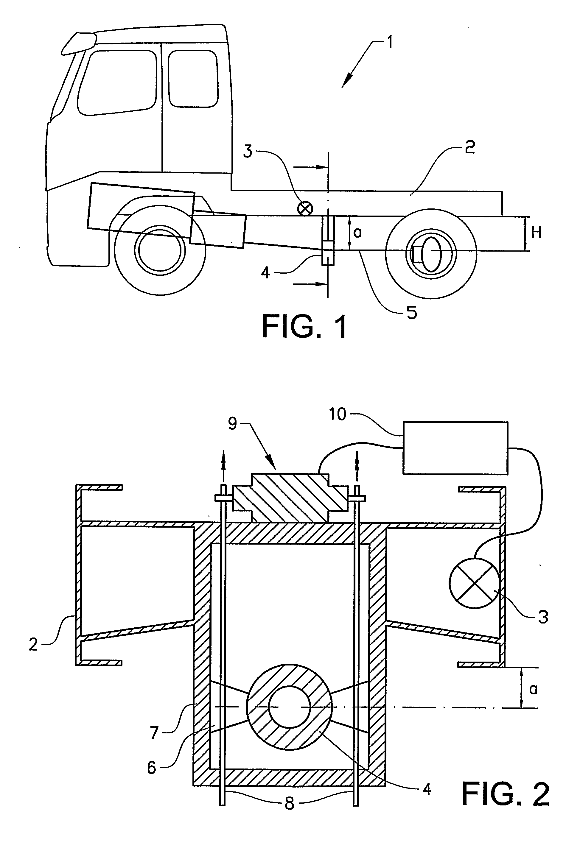
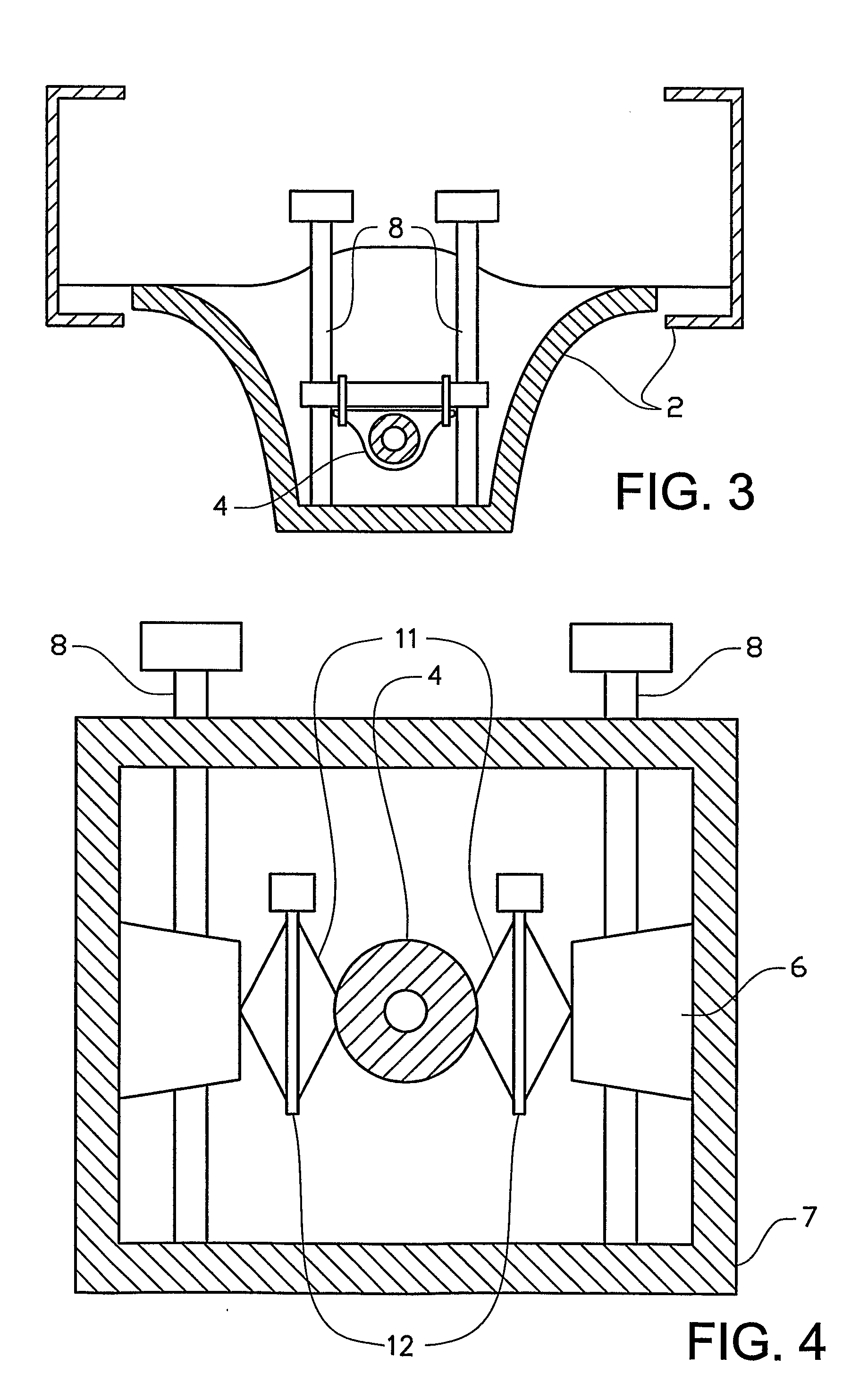
[0003] An object of the present invention is to provide control of the propeller shaft geometry to minimise variations in the torque and force, and thereby the resulting vibrations of the propeller shaft. This will both increase the durability of the propeller shaft components and improve the driver's working environment, which may be obtained in all loading conditions for the propeller shaft and for different chassis height adjustments. It also enables that the dispersion of the installation from the factory can be adjusted to the optimal position.

[0004] The present invention relates in a first aspect to a system for control of driveline geometry of a heavy vehicle, wherein the propeller shaft is suspended in a centre bearing unit the position of which can be adjusted, characterised in that the adjustment is determined based on one or more measurements of one or more geometrical parameters of the vehicle and the chassis acceleration.

[0005] In most preferred embodiments of the pre...


PUM


Abstract

A system for control of driveline geometry of a heavy vehicle includes a propeller shaft that is suspended in a center bearing unit, the position of which center bearing unit can be adjusted, wherein the adjustment is determined based on one or more measurements of one or more geometrical parameters of the vehicle and the chassis acceleration. A method for control of such a propeller shaft geometry and a heavy vehicle comprising such a system and/or by use of such a method are also disclosed.

Description

[0001] The present invention relates to control of the driveline geometry in heavy vehicles, and in particular to an continuous adjustment of a centre bearing unit, in which a propeller shaft is suspended, to give an optimal geometry during driving of the vehicle. BACKGROUND OF THE INVENTION [0002] The engine and transmission of a heavy vehicle are connected to a rear axle by a shaft, often referred to as a cardan shaft or more common as a propeller shaft, for transmission of a rotational moment to the rear axle. The propeller shaft has universal joints at the ends to compensate for the propeller shaft angles. The propeller shaft angles vary, e.g. when the vehicle is loaded, which may result in unbalances in the system whereby the ends of the propeller shaft rotationally accelerate and decelerate at different rates. The resulting vibrations lead to noise, increased wear, and discomfort for the driver. It is well known in the art to compensate for these unbalances e.g. by use of an a...

Claims


Application Information

Patent Timeline
Patent Type & Authority Applications(United States)
IPC IPC(8): B60K17/24G06F19/00B60K
CPCB60K17/24B60W2550/402B60W2510/104B60W2556/50
Inventor JOHANSSON, INGEHENSTROM, JOHNEDLUND, STEFAN
Owner VOLVO LASTVAGNAR AB
Why Eureka
Try Eureka