Pattern cutter

a pattern cutter and pattern technology, applied in the field of pattern cutters, can solve the problems of inability to cut non-uniform circular patterns, inability to meet the needs of customers, and inability to meet the needs of customers, and achieve the effect of smooth cutting any number of varying circular patterns

Inactive Publication Date: 2008-01-31
THE BANK OF NEW YORK MELLON AS ADMINISTATIVE AGENT
View PDF6 Cites 5 Cited by
  • Summary
  • Abstract
  • Description
  • Claims
  • Application Information

AI Technical Summary

Benefits of technology

[0011]The present invention looks to overcome the drawbacks associated with the prior art by providing a circle pattern cutting device having a cutting tool and an accompanying template, such that the cutting tool is configured to be guided around the template so as to smoothly cut any number of varying circular patterns into the desired substrate.

Problems solved by technology

However, devices such as these are generally restricted to cutting circle patterns in fairly standard, uniform dimensions.
However, these devices also suffer from several drawbacks as well.
For example, the prior art circle cutting devices, although capable of cutting non-uniform circular patterns, typically are provided with a cutting blade that is fixed in relation to its template guides.
By fixing the distance between the guides and the cutting blade, the cutting device is limited in terms of the number or variations in patterns that can be cut by a single cutting tool.
In both cases, the use of a guide means to guide a cutter around a template is restricted in that the distance between the guide means and the cutting blade is fixed, thus limiting the versatility of the cutter and of the types of patterns that can be used on the template.
Additionally, another drawback common amongst the prior art cutting devices for use on templates, is that their rotation about the template is often cumbersome and difficult because of the interaction between the guides and the track.
Because the height of the device from the template provides for a high center of gravity, the movement of the cutting tool around the template is often prone to jerky or otherwise unstable movements during circle cutting.

Method used


Image

  • Pattern cutter
  • Pattern cutter
  • Pattern cutter

Examples


Embodiment Construction

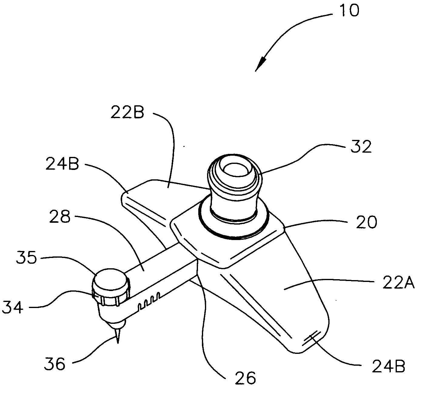
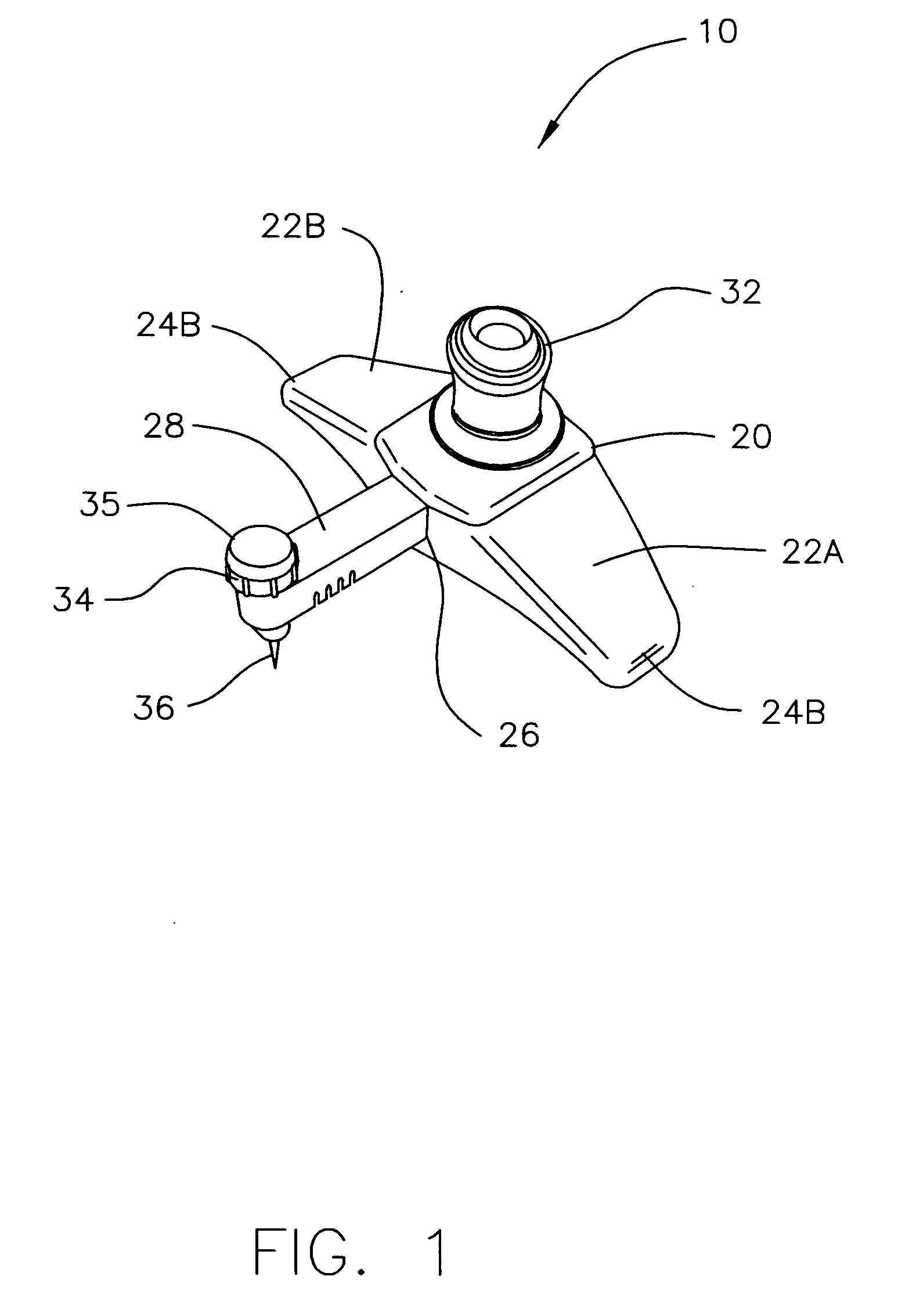
[0022]The present invention as illustrated in FIG. 1 is directed to a cutter 10 configured to be placed on a track template 14 shown in FIG. 4. Template 14 is in turn placed onto the desired substrate 16 as shown in FIG. 7 where cutter 10 is moved around template 14, such that cutter 10 cuts the desired circle pattern into substrate 16.

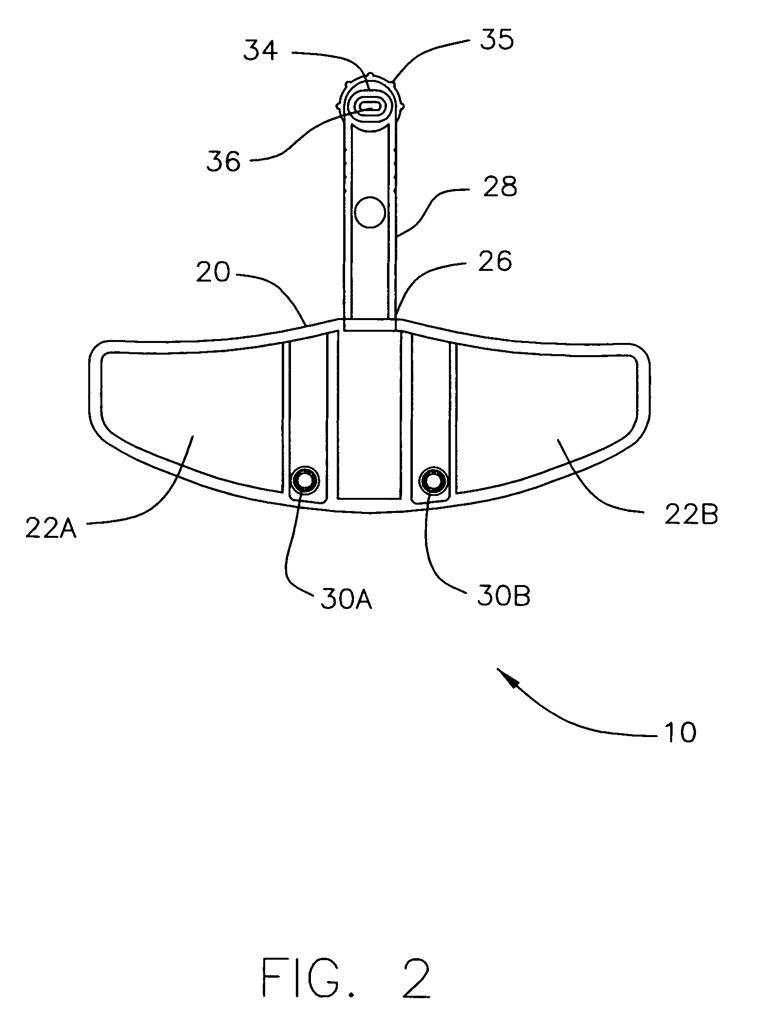
[0023]In one embodiment of the present invention, as illustrated in FIGS. 1 through 3, cutter 10 is comprised of a base portion 20 having first and second wing shaped supports 22a and 22b. First and second wing shaped supports 22a and 22b extend substantially perpendicularly away from base portion 20, configured to extending parallel to and flush against an upper surface 40a of template 14 as discussed below. (See FIG. 7) First and second wing shaped supports 22a and 22b may maintain a concave curvature similar to the general shape of template 14, such that the supports are disposed above template 14 as cutter 10 is moved, but the invention is not lim...


PUM

PropertyMeasurementUnit
heightaaaaaaaaaa
depthaaaaaaaaaa
pressureaaaaaaaaaa

Abstract

A cutter for cutting a pattern in a substrate, said cutter having a base and guide pins disposed on the bottom of the base. The guide pins are placed in a groove on a template. A longitudinally adjustable member supports a blade unit for cutting the pattern into the substrate, where the adjustable member is configured to be slidably positioned within a center track opening region movable towards and away from the guide pins.

Description

FIELD OF THE INVENTION[0001]The present invention is directed towards a pattern cutter. More particularly, the present invention is directed to an improved pattern cutter for cutting patterns such as circles or other designs, into a substrate.BACKGROUND OF THE INVENTION[0002]A compass is the most common tool used by people to draw and cut circles into a substrate, but there have been different auxiliary instruments developed to facilitate the drawing or cutting of circles of various diameters and variations such as a standard circle board on which circles of various sizes are orderly distributed with their diameters marked beside each hole so as to permit people to make circle cuttings with ease. However, devices such as these are generally restricted to cutting circle patterns in fairly standard, uniform dimensions.[0003]One example of such a device is found in U.S. Pat. No. 6,286,216, issued to Braun that provides a tool for making circular cuts. The tool comprises a relatively st...

Claims


Application Information

Patent Timeline
Patent Type & Authority Applications(United States)
IPC IPC(8): B26D7/00
CPCB26F1/3846B26B29/06Y10T83/68
Inventor HSU, WALTER W.
Owner THE BANK OF NEW YORK MELLON AS ADMINISTATIVE AGENT
Why Eureka
Try Eureka