
Resist for electron beam and optical lithography

a technology of resist and electron beam, applied in the field of resist for electron beam and optical lithography, can solve the problems of poor adhesion to the substrate, pattern deformation, and certain limitations

Inactive Publication Date: 2014-11-06
COUNCIL OF SCI & IND RES
View PDF0 Cites 2 Cited by
  • Summary
  • Abstract
  • Description
  • Claims
  • Application Information

AI Technical Summary

Benefits of technology

The invention allows for the selection of different groups of atoms around the edges of a molecule, which can affect its properties. In this case, the dendrimers have three or six hydroxyl groups on the edge, and a linkage is added between them to improve adhesion. This allows for greater control and customization of the molecule's properties.

Problems solved by technology

Crosslinking of these systems during post exposure bake (PEB) results in the generation of small gas molecules such as water vapor and methanol, which may lead to pattern deformation especially at lower feature sizes.
It is extensively used for applications in lithography and for molding and packaging, however it suffers from certain limitations.
Debonding after post-baking and development results from poor adhesion to substrate.
Also cracking at the corners of the microstructures has been reported.
However, these resins suffer from brittleness, resulting from high cross link density, higher shrinkage and stress generated during crosslinking, which results in cracks and adhesion problems.
However, lithographic performance of polymeric resist is affected by many factors like high molecular weights, broad molecular weight distribution, chain entanglement which results in poor performance especially irregularity of patterns.

Method used


Image

  • Resist for electron beam and optical lithography
  • Resist for electron beam and optical lithography
  • Resist for electron beam and optical lithography

Examples


example 1

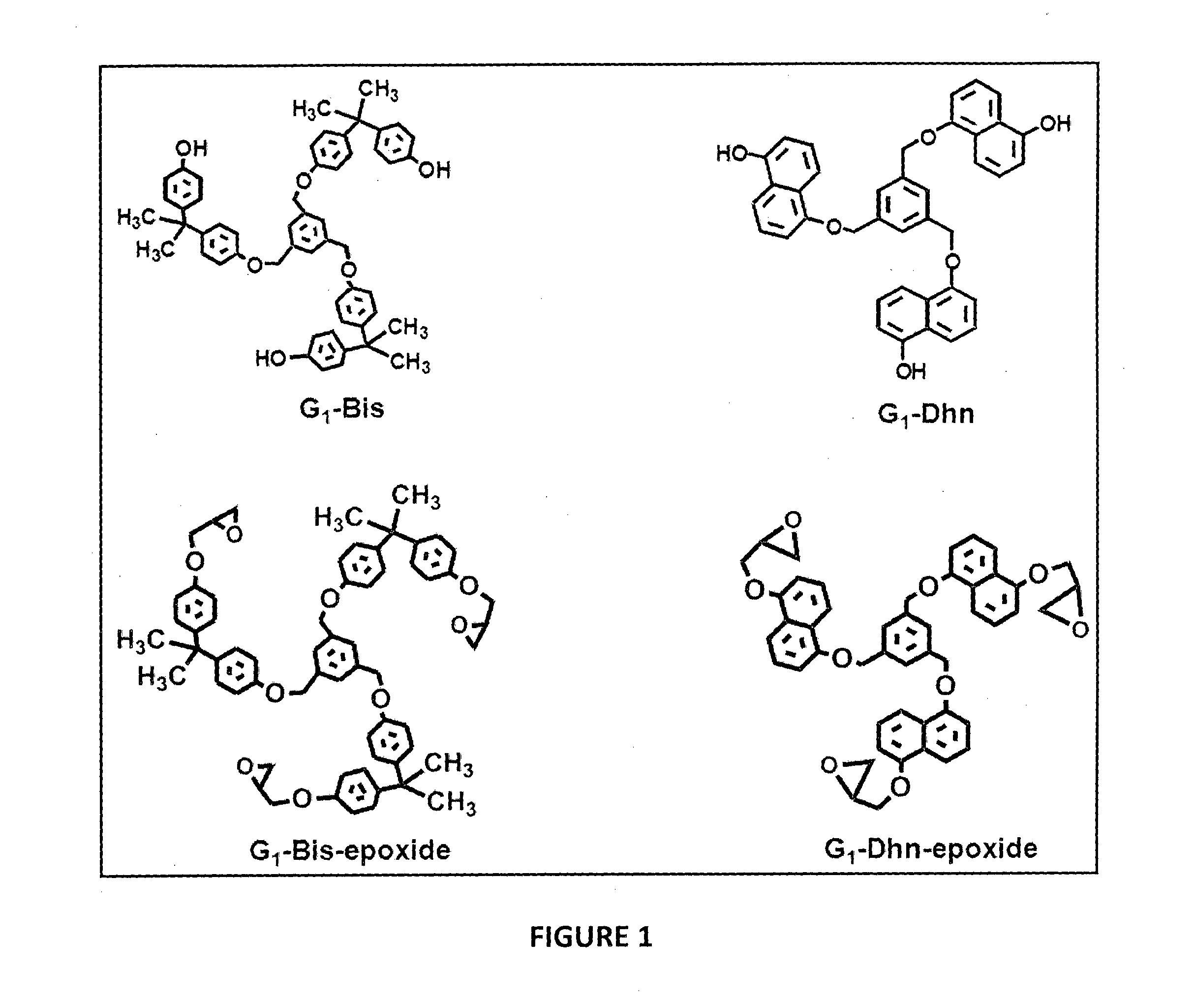
Preparation of G1-Tris

[0075]Trisphenol 47 g (0.156 moles) was dissolved in 400 ml DMF, 97 g (0.702 moles) of anhydrous potassium carbonate was added and stirred for 30 min and maintained at 65° C., 2.8 g (7.8×10⁻³ moles) of 1, 3, 5-trisbromomethyl benzene in 20 ml DMF was added drop wise over 40 min. After the addition was complete, stirring was maintained for 12 h. DMF was recovered on rotary evaporator and reaction mixture was extracted with ethyl acetate. The solvent was evaporated and the G1-Tris formed was purified by column chromatography, using petroleum ether and ethyl acetate (70:30 v / v) as elutant.G1-Tris yield was 8.50 g (85%).

[0076]1H-NMR spectrum of G1-Tris in acetone-4 indicate complete disappearance of the peak at 4.50 ppm corresponding to methylene in 1, 3, 5-trisbromomethyl benzene and appearance of the peak at 5.11 ppm confirms formation of G1-Tris. Peak at 9.28 ppm corresponds to the aromatic hydroxyl functionality of Trisphenol unit and at 7.52 ppm to the aromati...

example 2

Preparation of G1-Bis

[0077]25.5 g (0.112 moles) bisphenol-A, 47g (0.336 moles) of K2CO3 in 150 ml DMF and 2 g (5.6×10⁻³moles) of 1, 3, 5-trisbromomethyl benzene in 20 ml DMF were reacted as described above. G1-Bis yield was 5.00 g (87%).

[0078]1H NMR (DMSO-d6): 8.19 δ(3H, -OH), 6.7-7.19 (24H, phenolic protons), 7.56 (3H, benzylic protons), 5.13 (6H, Ph-CH2), 1.62 (18H, —CH3).

example 3

Preparation of G1-Dhn

[0079]18 g (0.112 moles) 1, 5-Dhn, 47 g (0.336 moles) of K2CO3 in 150 ml DMF and 2 g (5.6×10⁻³ moles) of 1, 3, 5-trisbromomethyl benzene in 20 ml DMF were reacted as described above G1-Dhn yield was 3.80 g (81%).

[0080]1H NMR (DMSO-d6): 9.10 δ(3H, —OH), 6.94-7.85 (18H, naphthalene ring protons), 7.88 (3H, benzylic protons), 5.42 (6H, Ph-CH2).


PUM

PropertyMeasurementUnit
Fractionaaaaaaaaaa
Fractionaaaaaaaaaa
Glass transition temperatureaaaaaaaaaa

Abstract

The present invention describes a first generation dendrimers useful in lithography, comprising 1,3,5-trisbromo-methylbenzene as the core and dense, bulky, rigid units selected from trisphenol (1, 1, 1-tris-p-4-hydroxyphenyl ethane), bisphenol-A and 1,5-dihydroxy naphthalene units at the periphery, wherein the peripheral aromatic rigid molecules are connected to the central core through an ether linkage.

Description

TECHNICAL FIELD OF THE INVENTION[0001]The present invention relates to a first generation dendrimer (FGD) comprising a core group and a peripheral moiety linked to the core wherein peripheral moiety has a functional group which has been chemically modified for a resist application.BACKGROUND AND PRIOR ART OF THE INVENTION[0002]Potential applications of dendrimers are based on their molecular uniformity, multifunctional surface and presence of internal cavities. These properties make dendrimers suitable for a variety of high technology applications in in vitro diagnostics; as contrast agents for magnetic resonance; in the targeted delivery of therapeutic agents; as coating agents to protect or deliver drugs to specific sites in the body or as time-release vehicles for biologically active agents, as carriers in gene therapy and industrial applications such as catalysts or as resists in electron beam as well as optical lithography.[0003]A photoresist is a light-sensitive material used ...

Claims


Application Information

Patent Timeline
IPC IPC(8): G03F7/027C07C41/01C07D303/28C07C43/23
CPCG03F7/027C07C43/23C07C41/01C07D303/28G03F7/038G03F7/039C08G83/003
Inventor KULKARNI, MOHAN GOPALKRISHNASANGAVE, DADASAHEB VITTHAL
Owner COUNCIL OF SCI & IND RES
Learn More