Bin lid closing device

a lid closing and bin lid technology, applied in the field of bin lid closing devices, can solve the problems of blown open bins at windy sites, such as coastal or valley sites, and unwanted odours in bins that are more noticeable, and can spread disease or rubbish around the local environment,

Active Publication Date: 2018-05-24
SHERRARD
View PDF13 Cites 1 Cited by
  • Summary
  • Abstract
  • Description
  • Claims
  • Application Information

AI Technical Summary

Benefits of technology

[0015]More preferably, the intermediate portion may comprise a helical spring having at least one coil, and more preferably a plurality of coils.
[0016]The number of coils can be varied to suit a required specification and to provide the required degree of strength to the device. The helical spring is desirably a helical torsion spring.

Problems solved by technology

This can be undesirable for a number of reasons.
Also, if the lid remains open, unwanted odours within the bin might be more noticeable.
In addition, if the bin is not fully emptied, vermin and pests, such as birds, mice, rats, insects etc. can be attracted to the rubbish, with the potential to spread disease or spread the rubbish from the bin around the local environment.
Furthermore, bins at windy sites, such as coastal or valley sites, or between buildings, tend to be blown open, particularly if the bin lid is not fully closed (often due to the bin being overfilled and the lid ‘propped’ open by the pile of rubbish above the top edge of the body of the bin).
An example of such a device is often known as a ‘wheelie bin stand.’ Typically, such devices, commonly used for bins located in public spaces, secure the bin and restrict ability to open the lid.
Such devices therefore limit what may be put into the bin, since the size of some articles will be too great to fit through the gap.
These types of devices are therefore unsuitable if the bin is intended to receive relatively larger articles or if it desired to have the ability to fully open the lid.
This can be both inconvenient and impractical since the device needs to be unclipped prior to the bin being put out for collection.

Method used


Image

  • Bin lid closing device
  • Bin lid closing device
  • Bin lid closing device

Examples


Embodiment Construction

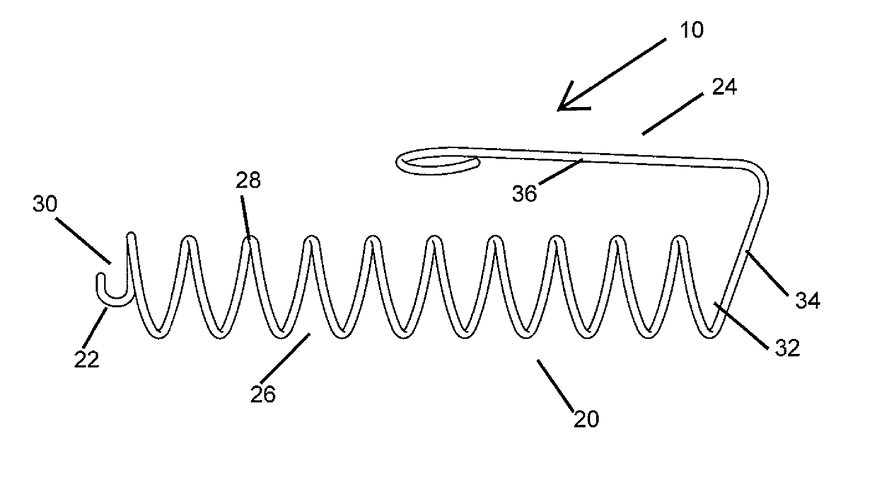
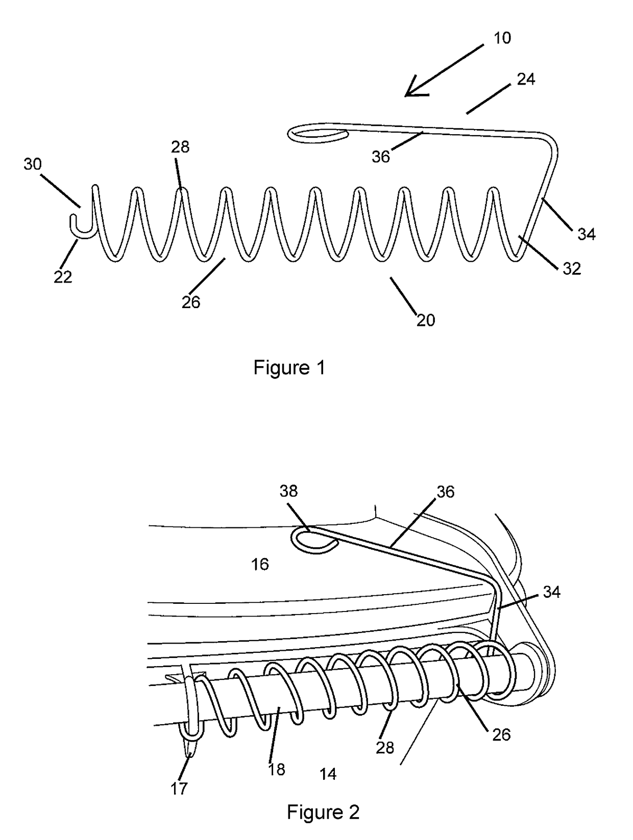
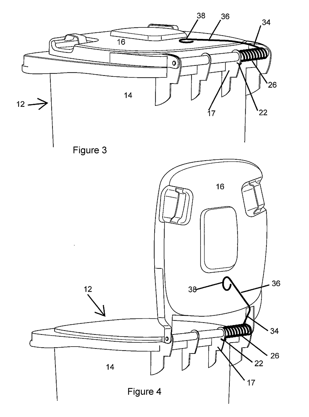
[0060]Referring initially to FIGS. 1 to 4, there is shown a first embodiment of a bin lid closing device 10 for use on a bin 12 of known type, an example of which is often referred to as a ‘wheelie’ bin. However, it should be understood that the device 10 is suitable for use with any type of bin that has a lid hingedly attached thereto. The bin 12 comprises a body 14 formed generally from four side walls, defining a receptacle which typically holds rubbish and / or recyclables; and a lid 16. A cylindrical handle 18 is provided adjacent an upper end of a rear side wall of the bin 12. In the embodiment shown in FIGS. 3 and 4, the cylindrical handle 18 extends substantially along the length of the upper end of the rear side wall. The handle 18 is divided into substantially equal portions, each divided by a rib or fin 17, which extends outwardly substantially perpendicularly from the rear side wall of the bin 12 and has a portion that encircles the handle 18. The lid 16 is pivotally secur...


PUM


Abstract

A device for use on or with bins for the purpose of returning a bin lid to a closed position and/or to retain a bin lid in a closed position. The device includes a lid engaging portion, a bin engaging portion and an intermediate portion between the lid engaging and bin engaging portions. The intermediate portion is arranged, in use, around, within and/or adjacent to a handle of the bin. The bin engaging portion extends outwardly from the intermediate portion. The lid engaging portion extends outwardly from the intermediate portion. The lid engaging portion is movable between a first (lid is closed) and a second (lid is at least partially open) position. The intermediate portion provides resistance to the lid as the lid engaging portion is moved from the first position towards the second position causing the lid engaging portion to bias the lid towards a closed position.

Description

FIELD OF THE INVENTION[0001]The present invention relates to a device for use on bins to return a bin lid to a closed position and / or retain a bin lid in the closed position.BACKGROUND TO THE INVENTION[0002]Bins at residential sites, commercial sites and municipal public sites for household, municipal garden and public space rubbish and recyclables, are generally collected by trucks with an automated mechanism for lifting and emptying. A common type of bin is frequently referred to as a ‘wheelie bin’. However, trucks can also collect other types of bins, also having a bin lid hingedly attached to a body of the bin.[0003]The mechanism includes an arm which lifts and upturns the bin such that the lid of the bin falls open and the contents of the bin fall into the rubbish container of the truck. When the bin has been emptied into the truck, the mechanism is controlled to return the bin upright and replace it on the ground, and then release the bin.[0004]Often when the emptied bin is re...

Claims


Application Information

Patent Timeline
Patent Type & Authority Applications(United States)
IPC IPC(8): B65F1/16
CPCB65F1/1623B65F1/1615
Inventor SHERRARD, JANELLE FAYE
Owner SHERRARD
Why Eureka
Try Eureka