Spotter scope

a technology of spotter scope and scope, applied in the field of spotter scope, can solve the problems of inability to observe the trace trajectory, extremely difficult to observe the trace, and large errors in the trace observation, so as to reduce the workload of spotter/sniper and improve the trace spotting analysis

Inactive Publication Date: 2008-01-31
HONEYWELL INT INC
View PDF20 Cites 21 Cited by
  • Summary
  • Abstract
  • Description
  • Claims
  • Application Information

AI Technical Summary

Benefits of technology

[0005] The present invention provides systems and methods for automatically generating an aim point correction f

Problems solved by technology

Observing target can only be performed during daylight and the trace is extremely difficult to observe even under ideal daylight conditions.
Tra

Method used


Image

  • Spotter scope
  • Spotter scope
  • Spotter scope

Examples


Embodiment Construction

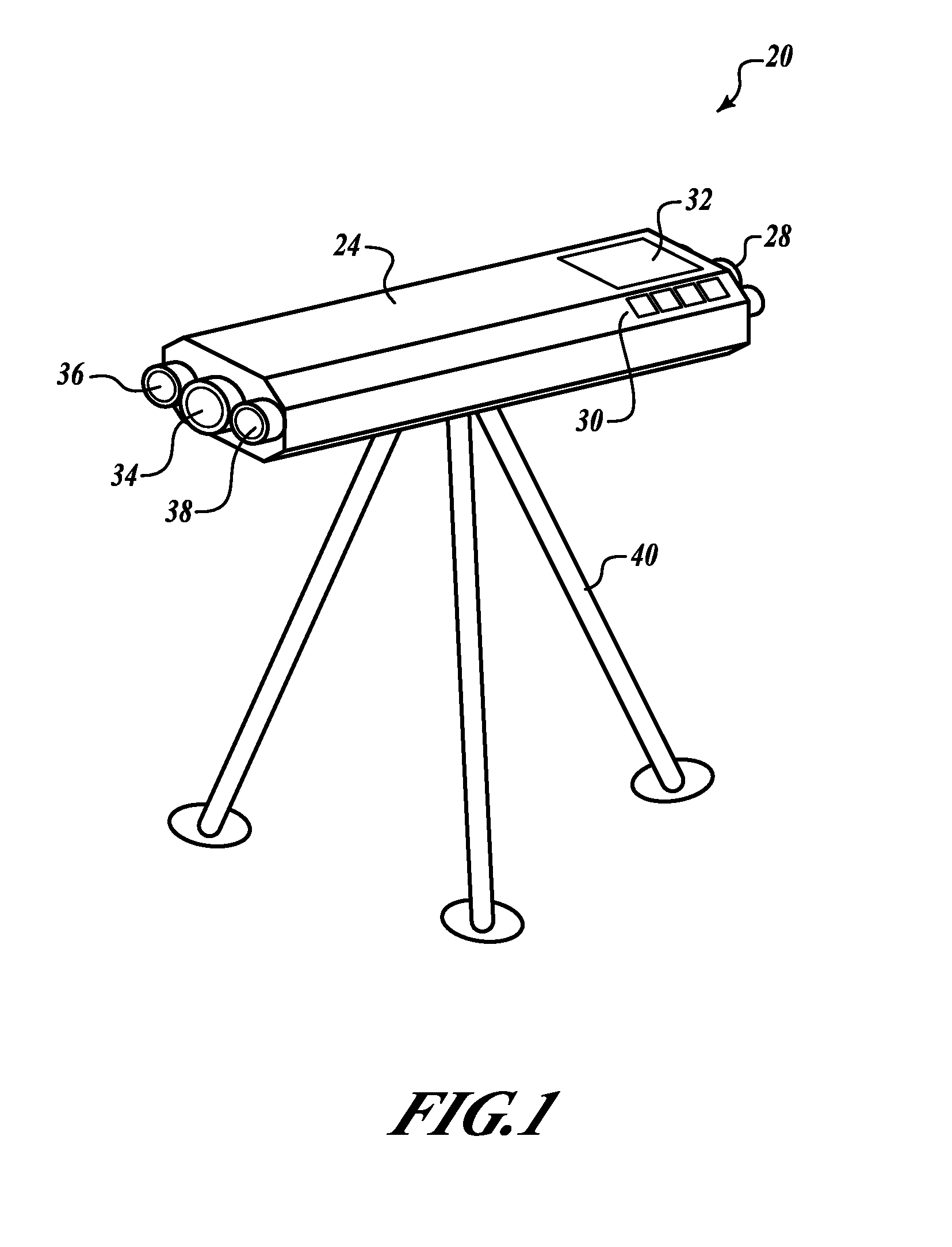
[0015]FIG. 1 shows an example spotter scope 20 formed in accordance with an embodiment of the present invention. The scope 20 may be hand-held or mounted to a support device, such as a tripod 40. The scope 20 includes a housing 24 with a scope lens 34, a video lens 36, and an infrared lens 38 located at a first end of the housing 24. At a second end of the housing 24 are eye pieces 28 that correspond to the lenses 34-38, user interface controls 30, and a display device 32.

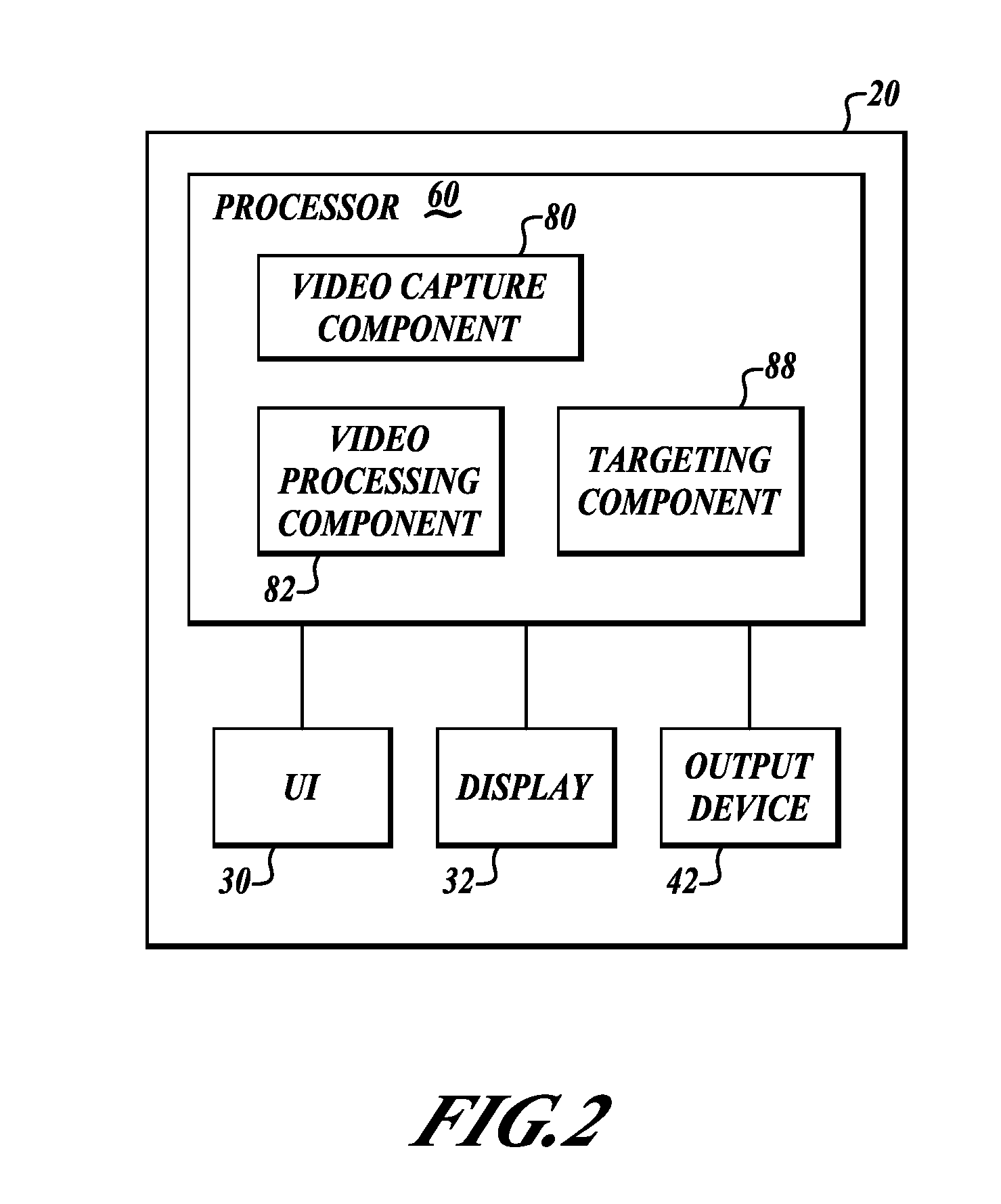
[0016] As shown in FIG. 2, the scope 20 includes a processor 60 that is in data communication with user interface controls 30, the display device 32, and an output device 42. An example of the output device 42 is a digital micro mirror device (DMD) that is controlled by a Digital Signal Processing (DSP) chip for presenting images in the field of view through the scope lens 34 and via an associated eye piece.

[0017] In one embodiment, the processor 60 includes video capture components 80, video processing component...


PUM


Abstract

Systems and methods for automatically generating an aim point correction for sniper operations. The present invention reduces spotter/sniper workload and improves trace spotting analysis. An example system includes a scope, a video capture component, an output device, and a processor in signal communication with the video capture component and the output device. The video capture component captures video of a bullet from when the bullet left a weapon to at least when the bullet crossed a previously determined target range. The processor determines from the captured video where the bullet was located relative to an intended target when the bullet was at the target range, generates a new aim point if the bullet was determined to have missed an intended hit point, and outputs the generated new aim point to the output device.

Description

PRIORITY INFORMATION [0001] This application claims priority to provisional patent application Ser. No. 60 / 746,736 filed on May 8, 2006 and is incorporated herein by reference.BACKGROUND OF THE INVENTION [0002] U.S. military sniper teams generally consist of a shooter and an observer (or spotter). The observer uses a non-electronic glass optics-based spotting scope to observe a target, determine distance, and estimate wind speed and direction before a shot is fired. The spotter conveys this information to the shooter for point of aim adjustments prior to shooting. Distance is estimated manually. [0003] After the shooter fires, the spotter tries to observe the actual path of the bullet (trace) to the intended target (point of impact) through the spotting scope. The spotter then attempts to determine if the target was hit based on the observed trace trajectory. If the target was not hit, the spotter determines where the bullet crossed the plane of the target and suggests an aiming cor...

Claims


Application Information

Patent Timeline
IPC IPC(8): F41G3/00F41G1/38
CPCF41G1/38F41G3/142F41G3/02F41G1/46
Inventor DREXLER, JEROME P.CORNETT, ALAN G.BECKER, ROBERT C.
Owner HONEYWELL INT INC
Why Eureka
Try Eureka