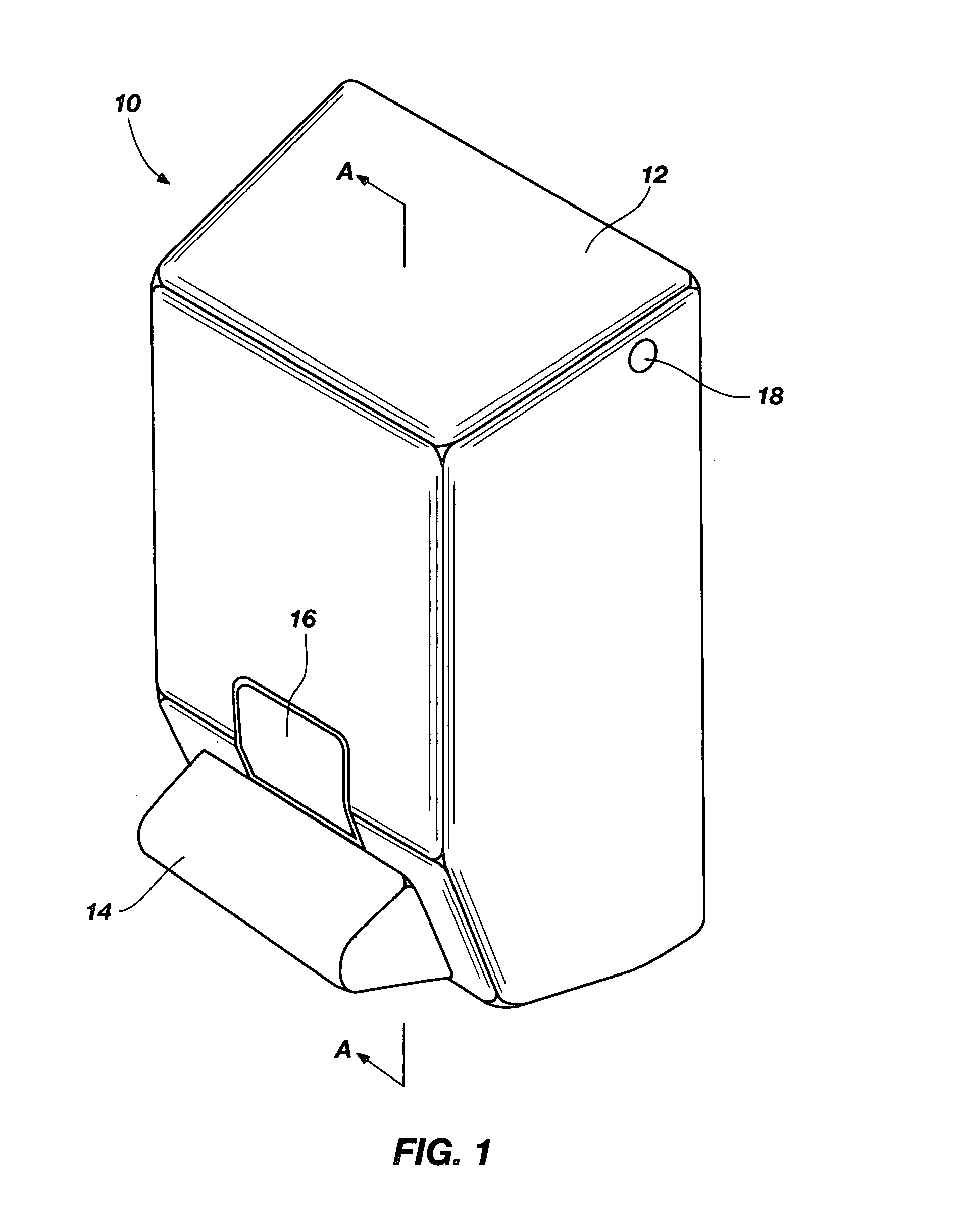
[0014] A dispenser according to the present invention may include a housing for removably accommodating an
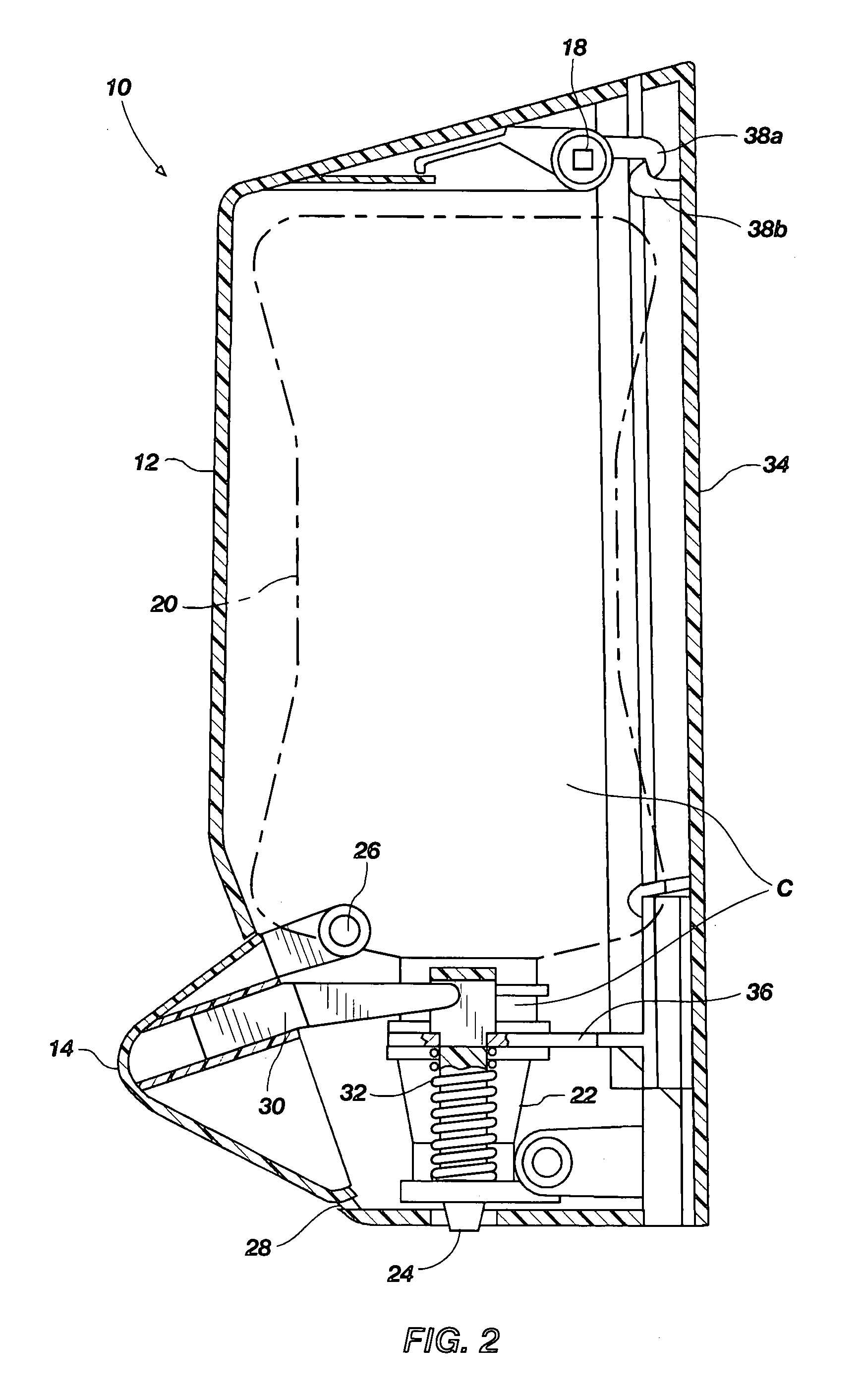
assembly that includes a collapsible reservoir and a pump. The collapsible reservoir is configured to contain a liquid product. The pump is connected to the reservoir and is configured to dispense a fluid product using the liquid product as an input. When the assembly is accommodated in the housing, the pump may be located at the underside of the reservoir. The liquid product may be withdrawn by the pump from the reservoir without a substantial gas flow back into the reservoir. The dispenser may further include actuating means for actuating the pump so as to dispense fluid from the pump to the exterior of the assembly. In addition, a dispenser that incorporates teachings of the present invention may be configured to help reduce waste of liquid product, such as liquid product that may otherwise be trapped in a collapsible reservoir.
[0016] Since bulging of a collapsible reservoir may be caused by the act of (partially) filling an empty reservoir that is relatively flat to start off with, a constant attempt to negate this bulging may thus amount to a constant attempt to revert the reservoir to flatness and emptiness. Stated another way, the tensioning means in the housing according to the invention may actively squeeze liquid product out of the reservoir, rather than just passively relying on gravity to cause as much liquid product as possible to migrate toward the pump. By applying a tensile force along the second direction, the bulging of the reservoir is pulled inward in a substantially homogeneous manner, thus decreasing the risk that excessive crumpling of the reservoir will occur, and therefore reducing the attendant risk of liquid product getting trapped in the internal folds, corners, etc., arising from such crumpling.
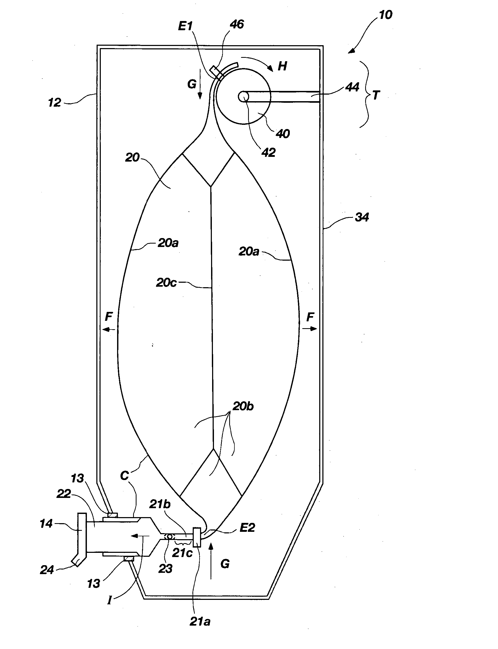
[0017] In an embodiment of a dispenser according to the invention, the tensioning means may include suspending means for suspending the reservoir by a first extremity so that it hangs under the force of gravity, the pump being attached to a second extremity of the reservoir located opposite the first extremity. Because the reservoir is hung up in the housing rather than, for example, sitting on a retaining shelf, the weight of the reservoir and its contents apply a tensioning force to the reservoir along the vertical direction (second direction), thus serving to counteract the (net) outward bulging of the reservoir in the horizontal direction (first direction).
[0024] The pump may include a liquid
inlet valve for admitting liquid product into the pump from the reservoir, the influx of liquid product through the valve occurring along a flow axis; and the housing comprises clamping means for clamping the pump in a given posture, whereby the pump is thus postured by the clamping means that the flow axis is substantially horizontal. When the pump is actuated so as to dispense fluid, the liquid
inlet valve may shut tightly so as to minimize migration of liquid product from the pump back into the reservoir. In the case of a liquid product containing a suspended granulate solid, a build-up of granulates within the liquid
inlet valve (e.g., between a
ball bearing / flap member / top hat member and a corresponding
valve seat, or in the
throat of a duckbill valve) can prevent the valve from shutting properly, and this can result in the creation of a substantial
dead volume upstream of the valve. However, by ensuring that the flow axis into the valve is substantially horizontal, such an accumulation of granulates in the valve may be minimized. It is believed that if a
buoyancy imbalance arises and granulates start to precipitate out of suspension, they will either sink downward (parallel to the direction of gravity) or float upward (anti-parallel to the direction of gravity). In the event of a vertical flow axis through the valve, a sinking effect would tend to cause a forward accumulation of granulates at the entrance side of the valve, whereas a floating effect would tend to cause a similar backward accumulation at the
exit side of the valve, either of which would eventually lead to incorrect operation (jamming) of the valve. However, by arranging the flow axis to be horizontal (or, at least, substantially horizontal), the component of gravity along the flow axis is zero (or, at least, substantially zero), thus, it is currently believed, avoiding the accumulation effects described above.
[0025] As indicated in the opening
paragraph, when the assembly of reservoir and pump is accommodated in the housing, the pump is located at the underside of the reservoir. For example, a
throat may be provided at (or proximal to) the lowest point of the reservoir, and this
throat may be connected to the liquid inlet valve of the pump (see previous
paragraph) using a duct; see, e.g., the abovementioned U.S. Pat. No. 5,732,853. The inventor has observed that, in the case of
viscous liquid products as alluded to above, the distance H between the liquid inlet valve of the pump and the point at which the pump is attached to the reservoir is preferably kept as short as possible; for example, in the previous
sentence, said duct is ideally kept as short as possible (without sacrificing practicality). In this manner, pressure loss in the head H is kept to a minimum, so that the ability of the pump to suck liquid product out of the reservoir is optimized. This helps achieve a further reduction in the amount of liquid product trapped in the reservoir.

