Thrust roller bearing

a technology of roller bearings and rollers, applied in the direction of bearing components, shafts and bearings, mechanical equipment, etc., can solve the problems of increasing the heat value of the contact part between the pocket wall surface at the time of bearing rotation, and the wear generated by drilling at the contact part between the outer end face of the roller in the diameter direction, so as to reduce the heat value of the contact part between the roller and the pock

Inactive Publication Date: 2008-01-31
NTN CORP
View PDF3 Cites 6 Cited by
  • Summary
  • Abstract
  • Description
  • Claims
  • Application Information

AI Technical Summary

Benefits of technology

[0014]According to the present invention, since the guide part is moved to the inside in the diameter direction, the movement of the outer end face of the roller in the diameter direction becomes free. As a result, the heat value at the contact part between the roller and the pocket is lowered and the thrust roller bearing can have a long life under the high-speed rotation and rare lubricant environments.

Problems solved by technology

Meanwhile, since the lubricant oil amount is reduced for low-fuel consumption in view of environments and the lubricant oil having low viscosity is used, the thrust roller bearing is used under increasingly harsh conditions.
Therefore, the wear (drilling wear) generated at the contact part between the outer end face of the roller in the diameter direction and the pocket wall surface at the time of bearing rotation has become a problem.

Method used


Image

  • Thrust roller bearing
  • Thrust roller bearing
  • Thrust roller bearing

Examples


Embodiment Construction

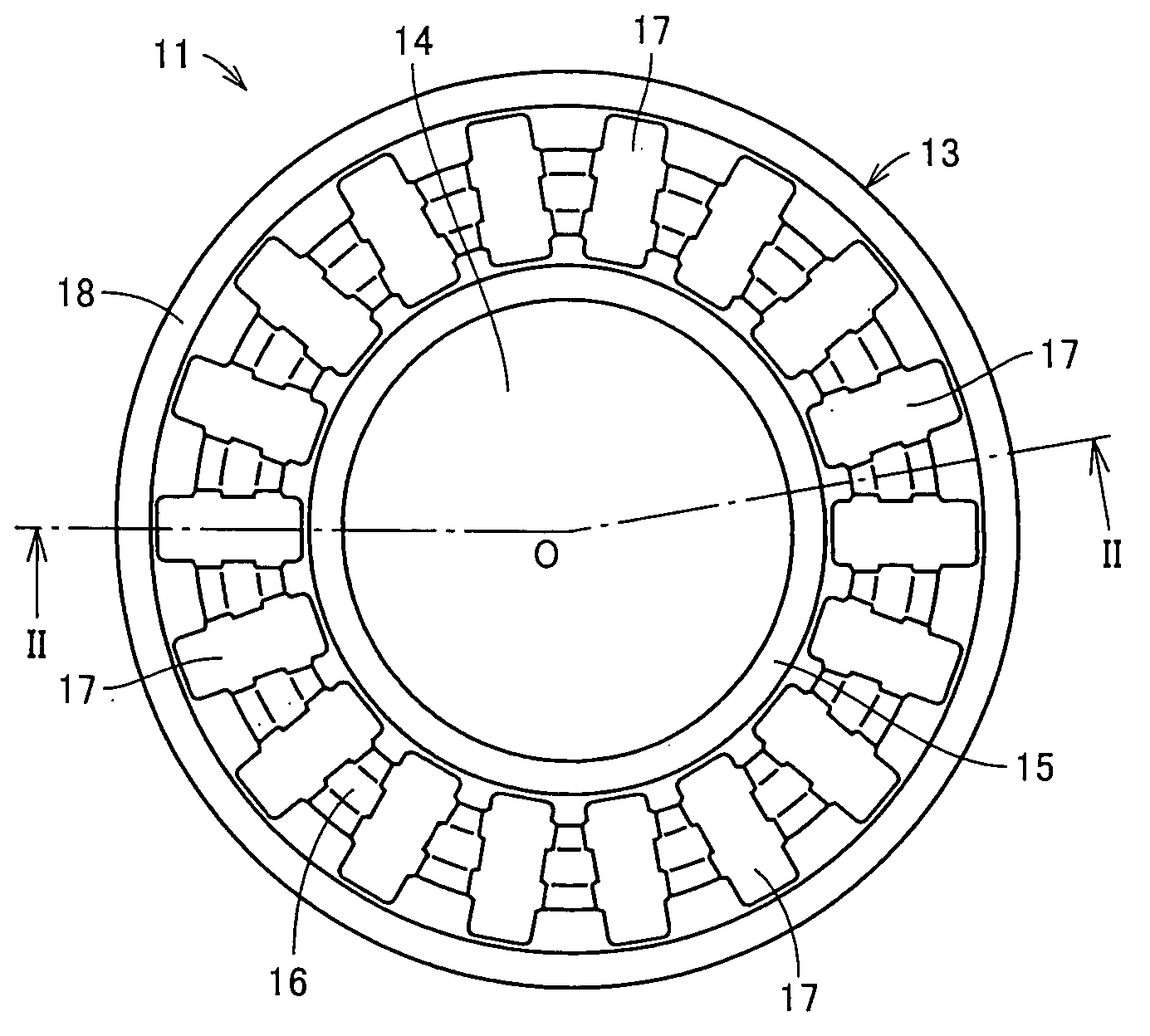
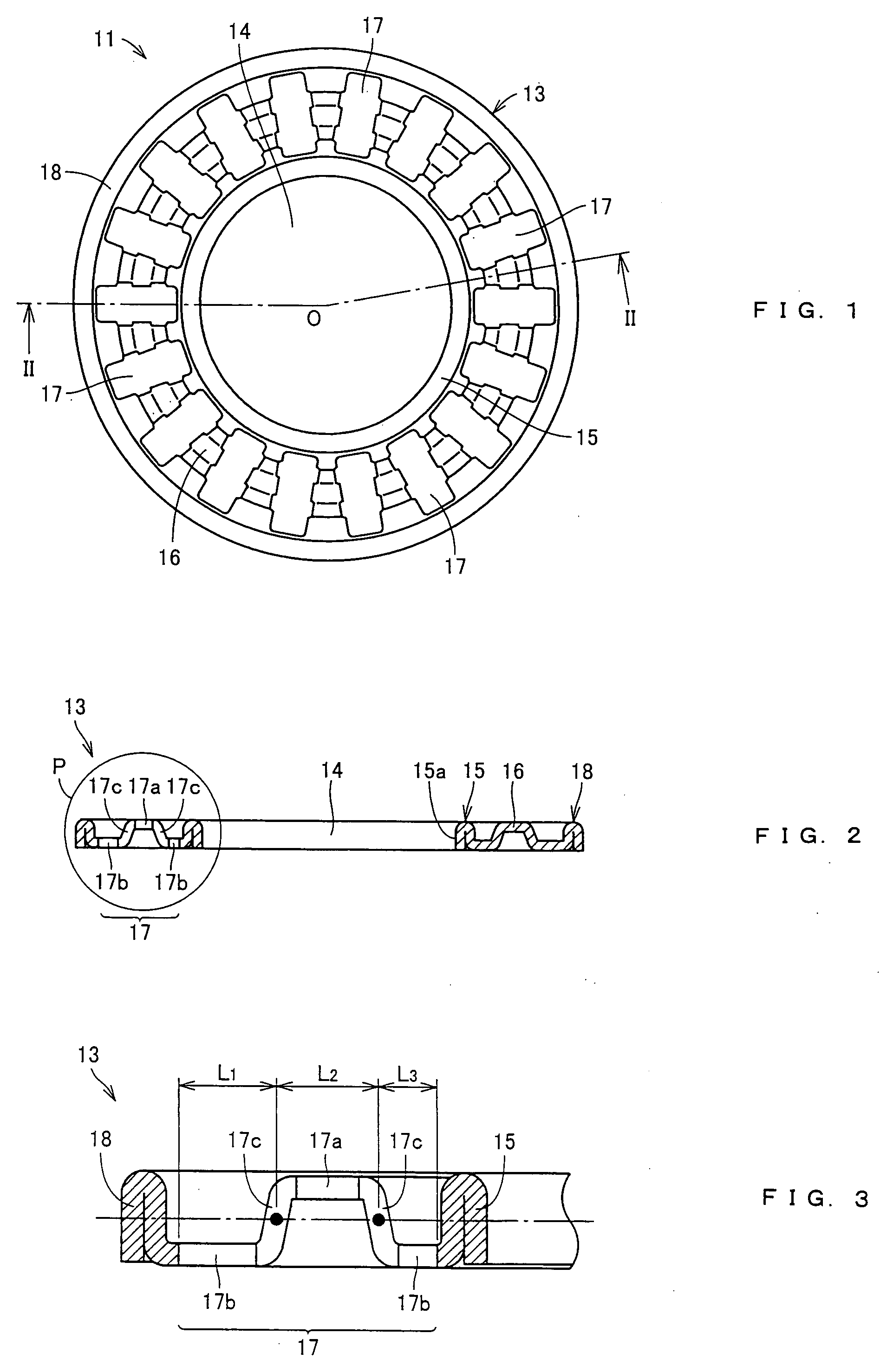
[0022]A thrust roller bearing 11 according to one embodiment of the present invention will be described with reference to FIGS. 1 to 3 hereinafter. In addition, FIG. 1 is a plan view showing the thrust roller bearing 11 according to one embodiment of the present invention, FIG. 2 is a sectional view taken along a line II-II in FIG. 1, and FIG. 3 is an enlarged view showing a part P in FIG. 2.

[0023]First, referring to FIG. 1, the thrust roller bearing 11 is a cage & roller type bearing comprising a plurality of rollers (not shown) and a cage 13 holding the intervals of the adjacent rollers, and it is mainly used in a compressor for a car air conditioner, an automatic transmission, a manual transmission, a hybrid car and the like.

[0024]Referring to FIG. 2, the cage 13 is a disk-shaped member in which a hole 14 is formed in the center and formed such that a metal flat plate is bent by pressing process and the like. Thus, it comprises an inner peripheral flange 15 formed along the outer...


PUM


Abstract

A thrust roller bearing comprises a plurality of cylindrical rollers each having a rolling surface on its side surface and a cage formed of a disk-shaped member having a hole formed in the center and comprising a plurality of pockets penetrating in a thickness direction for housing the rollers. The pocket has a plurality of stopper parts at a wall surface opposed to the rolling surface of said roller, and a plurality of guide parts between said adjacent stopper parts. When it is assumed that the distance between the outer wall surface of said pocket in the diameter direction and the guide part located on the outer side in the diameter direction of the two guide parts is L1 and the distance between the inner wall surface of said pocket in the diameter direction and the guide part located inner side in the diameter direction of the two guide parts is L3, it is satisfied that L1>L3.

Description

BACKGROUND OF THE INVENTION[0001]1. Field of the Invention[0002]The present invention relates to a thrust roller bearing and more particularly, to a thrust roller bearing used in a compressor for a car air conditioner, an automatic transmission, a manual transmission, a hybrid car and the like.[0003]2. Description of the Background Art[0004]A conventional thrust roller bearing 101 used in a compressor for a car air conditioner, an automatic transmission, a manual transmission, a hybrid car and the like is disclosed in Japanese Unexamined Patent Publication No. 2003-83333, for example. Referring to FIG. 7, the thrust roller bearing 101 disclosed in this document comprises a plurality of rollers 102, a track ring 103 holding the plurality of rollers in the axis direction and a cage 104 retaining the plurality of rollers 102.[0005]In addition, the cage 104 has a pair of ring parts 104a and 104b and a plurality of pillar parts 104c formed between the ring parts 104a and 104b, and a pock...

Claims


Application Information

Patent Timeline
Patent Type & Authority Applications(United States)
IPC IPC(8): F16C33/46
CPCF16C33/54F16C19/30F16C33/543F16C33/546
Inventor OBAYASHI, KOUSUKEYAMAMOTO, KAZUYUKI
Owner NTN CORP
Why Eureka
Try Eureka