Check patentability & draft patents in minutes with Patsnap Eureka AI!

Belt tensioner with installation pin

a technology of installation pin and tensioner, which is applied in the direction of belt/chain/gearing, mechanical equipment, belts, etc., can solve the problems of pin being loaded by the spring, difficult to remove pins, and difficult to install tensioners, so as to increase the tensioner stroke away and facilitate belt installation.

Inactive Publication Date: 2008-01-31
LITENS AUTOMOTIVE INC
View PDF4 Cites 23 Cited by
  • Summary
  • Abstract
  • Description
  • Claims
  • Application Information

AI Technical Summary

Benefits of technology

The design significantly eases belt tensioner installation by increasing the installation stroke, reducing the force required for pin removal, and preventing potential damage from impact forces, while maintaining operational effectiveness by allowing the pivot structure to pivot freely after installation.

Problems solved by technology

Because the eccentric adjusting member is located within the periphery of the tensioner pivot, its size is limited and the maximum linear stroke of the tensioner into and out of the drive system (approximately equal to twice the eccentricity of the eccentric member) may be insufficient to allow for proper installation of the belt.
Additionally, recent trends to increase the number of components in the timing drive system and to increase the tolerance range on belt dimensions, as well as requirements from engine OEM's that belts from more than one supplier (i.e., belts with different tolerances) can be used on the same timing drive system, make it very difficult for a tensioner equipped with a regular eccentric member to have enough installation travel to accommodate all situations.
A disadvantage of such “enhanced” design, however, is that the pin is loaded by the spring (because the pin is required to hold the pivot arm at the load stop position, away from the belt).
As a result, it can require significant force to remove the pin from the arm and the fixed component, which makes pin removal (and hence the tensioner installation procedure) difficult.
Furthermore, when the pin is removed and the pivoted structure is “released” to pivot freely, the pivoted structure may pivot all the way into contact with the tensioner free arm stop with significant impact force.
Such impact force can damage the internal components of the tensioner, particularly if the tensioner uses a high torque spring.

Method used


Image

  • Belt tensioner with installation pin
  • Belt tensioner with installation pin
  • Belt tensioner with installation pin

Examples


Embodiment Construction

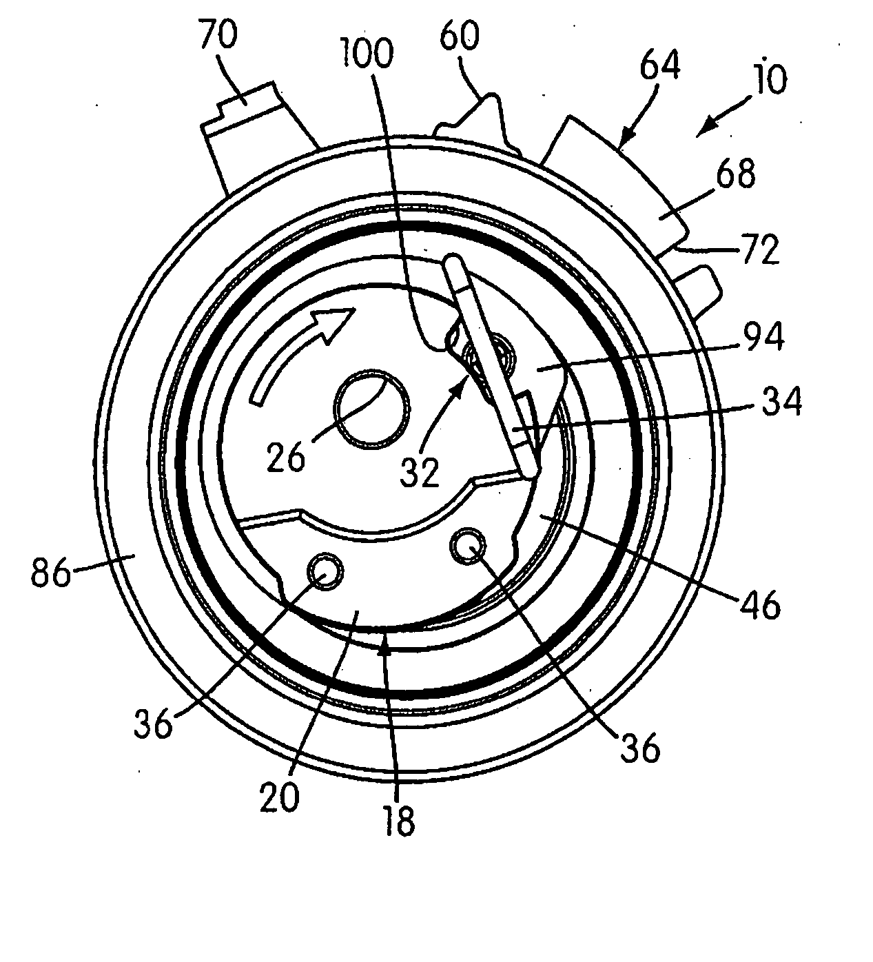
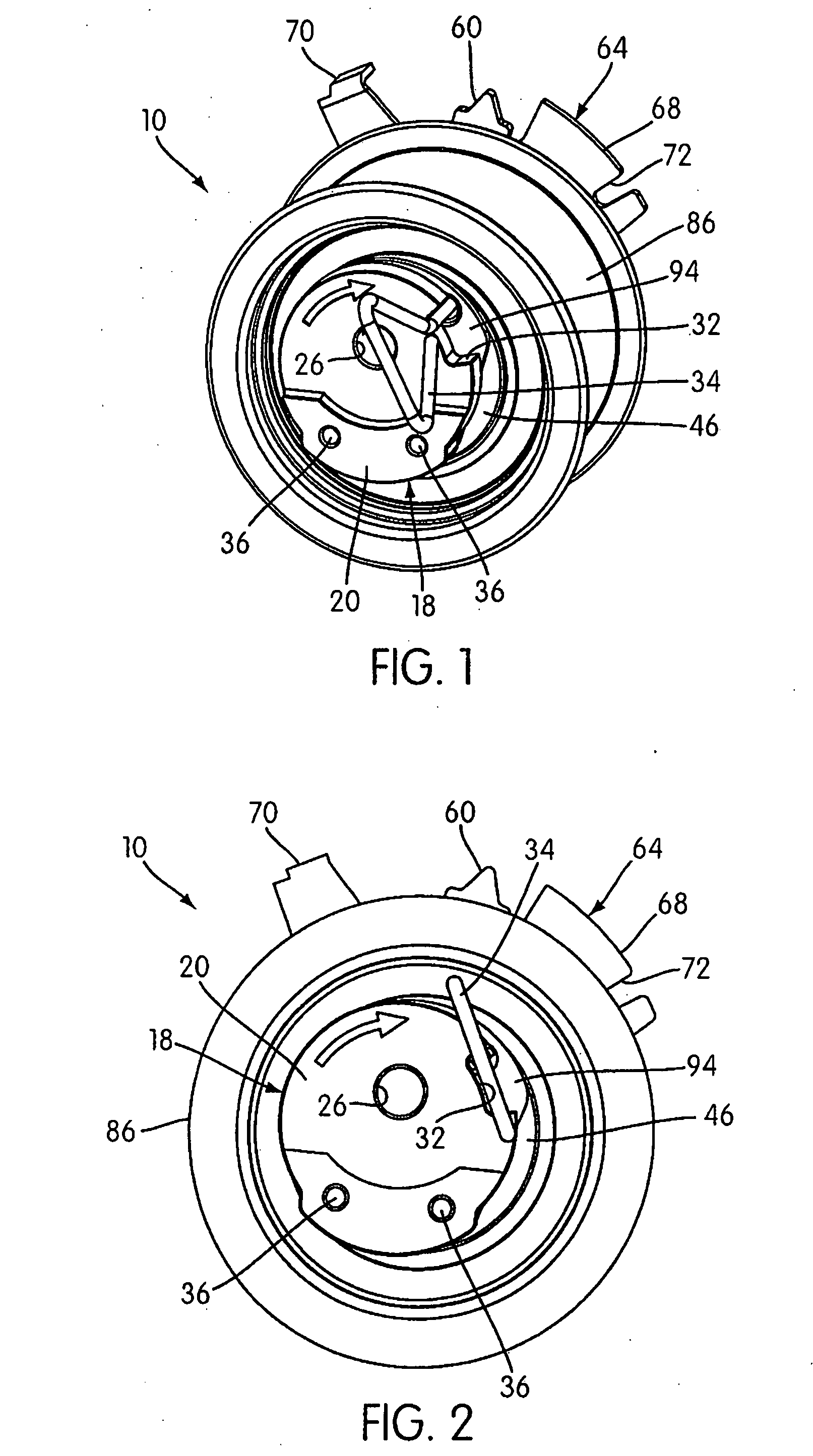
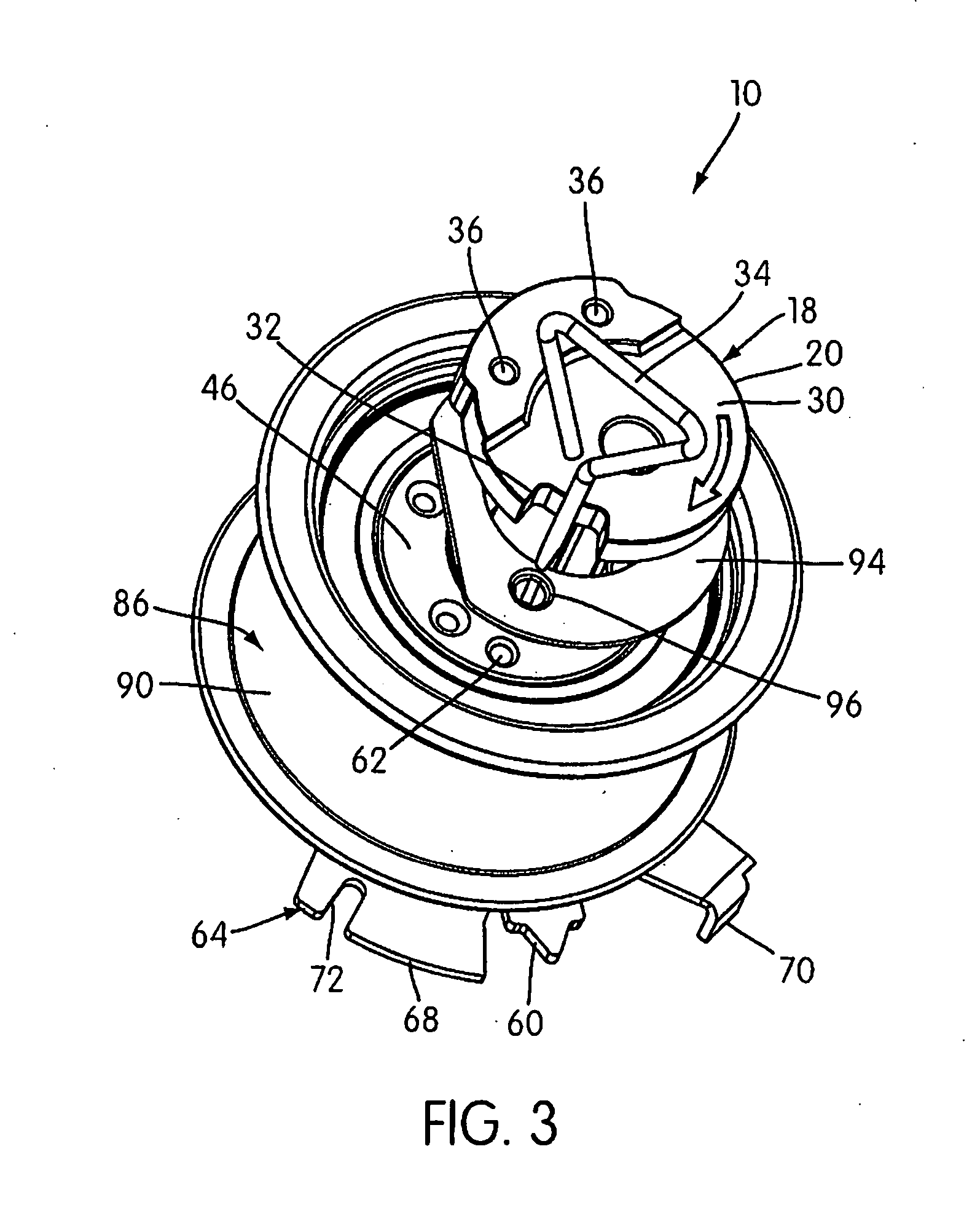
[0025] As illustrated in the drawings, a belt tensioner to which embodies the principles of the present invention mounted on an engine block or frame 12 by a threaded fixing bolt 14 (shown in FIG. 5) and is in tensioning engagement with a drive or timing belt 16 (shown in FIGS. 8 and 9). Alternatively, the engine block 12 may include a stud (not shown) extending from it on which the tensioner is mounted and to which the tensioner is secured by a nut. Other means of securing the tensioner 10 to the engine block 12 are also contemplated.

[0026] The tensioner 10 includes an inner, eccentric adjusting member 18 that is used to move the tensioner pivot structure (lever arm 46) toward and away from the belt 16. As illustrated, the eccentric adjusting member 18 can have a nested, two-component configuration. In particular, the illustrated adjusting member 18 consists of an inner installation shaft 20 and a surrounding, generally sleeve-shaped pivot shaft 22, which are secured together with...


PUM


Abstract

A belt tensioner for tensioning the belt of a belt drive system includes an eccentric adjusting member, a pivot structure eccentrically mounted on the adjusting member for pivoting around the adjusting member, a belt-tensioning pulley mounted to rotate on the pivot structure, a biasing member that resiliently biases the pivot structure in a belt-tightening direction, and a coupling structure. The coupling structure temporarily couples the pivot structure to the adjusting member to pivot with it during a belt installation procedure, and the configuration keeps the coupling structure unloaded except for a limited period of time during the installation procedure such that the coupling structure can be installed and removed easily. The tensioner is rendered operative after the pivot structure is uncoupled from the adjusting member, thus allowing the pivot structure to pivot with respect to the adjusting member.

Description

FIELD OF THE INVENTION [0001] The present invention relates to belt tensioners and, in particular, to belt tensioners that can be installed more easily and precisely as part of an automotive belt drive system. BACKGROUND OF THE INVENTION [0002] Belt tensioners are generally well known devices that have been used previously in many belt-drive systems. It is conventional practice to use a tensioner to apply a constant belt-tensioning force, which compensates for increases in belt length due to wear and other factors. A common type of conventional belt tensioner has a fixed structure and a pivoted structure eccentrically mounted on the fixed structure by means of a pivot assembly, and the pivoted structure has a belt-engaging pulley rotationally mounted on it. A coil spring surrounds the pivot assembly and has its ends connected between the fixed and pivoted structures so as to bias the pivot structure in a belt take-up direction. As the pivoted structure moves from a position of minim...

Claims


Application Information

Patent Timeline
Patent Type & Authority Applications(United States)
IPC IPC(8): F16H7/10F16H7/02F16H7/08F16H7/12F16H7/24
CPCF16H7/1281F16H7/24F16H2007/0878F16H2007/0846F16H2007/081F16H7/12
Inventor DINCA, FLAVIUTAO, YINCHUCOMSA, RARES I.
Owner LITENS AUTOMOTIVE INC
Features
  • R&D
  • Intellectual Property
  • Life Sciences
  • Materials
  • Tech Scout
  • Unparalleled Data Quality
  • Higher Quality Content
  • 60% Fewer Hallucinations
Learn More