Electrocardiogram Monitoring

a technology of electrocardiogram and monitoring device, which is applied in the direction of catheters, applications, therapy, etc., can solve the problems of poor electrical connection, inability to detect ecg signals, and insufficient quality of ecg signals for analysis

Active Publication Date: 2008-01-31
PHYSIO CONTROL INC
View PDF8 Cites 92 Cited by
  • Summary
  • Abstract
  • Description
  • Claims
  • Application Information

AI Technical Summary

Benefits of technology

[0006] In general, the invention is directed to techniques for detecting whether the leads coupled to an ECG monitoring device, e.g., the three leads coupled to a three wire electrocardiogram monitoring device, are adequately connected to a patient. More particularly, an ECG monitoring device according to the invention injects an integrated signal via one of the leads, and determi

Problems solved by technology

In the case of a patient with a hairy chest, for example, an electrode placed on the chest may lose contact with the patient's skin, resulting in a poor electrical connection.
An inade

Method used


Image

  • Electrocardiogram Monitoring
  • Electrocardiogram Monitoring
  • Electrocardiogram Monitoring

Examples


Embodiment Construction

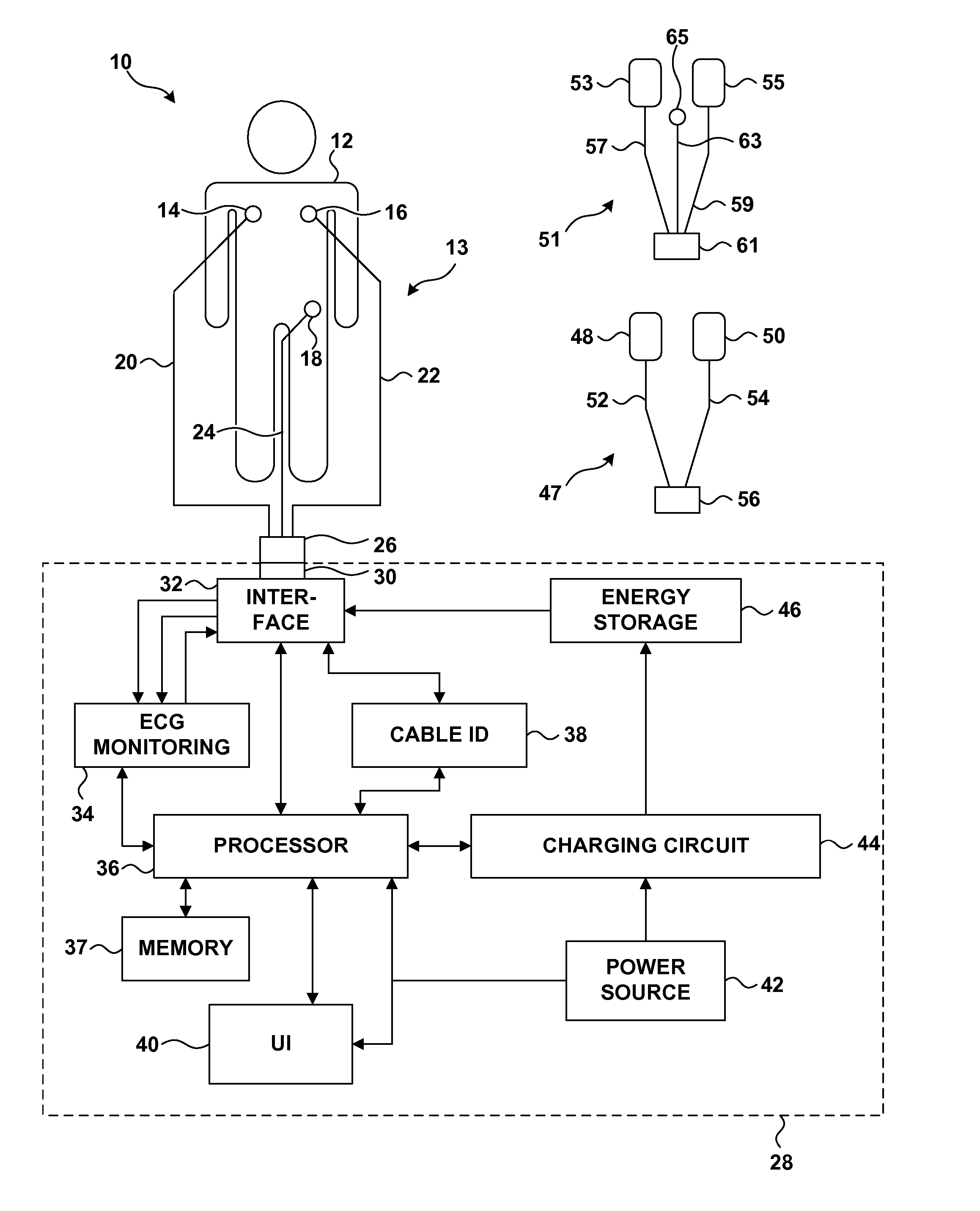
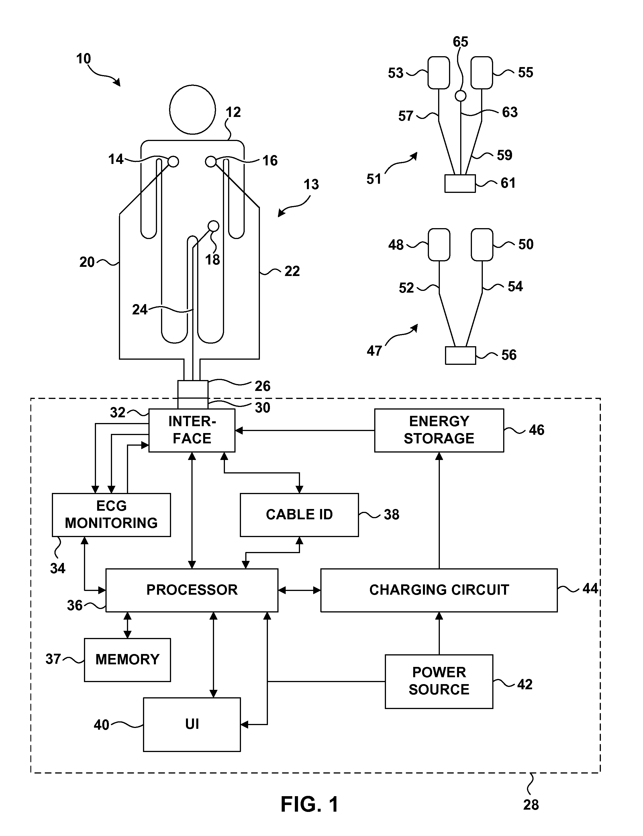
[0030]FIG. 1 is a block diagram illustrating an example system 10 including a defibrillator 28 coupled to a patient 12 by an elongated three-wire ECG monitoring cable 13. Cable 13 includes three leads 20, 22 and 24 that convey electrical signals between defibrillator 28 and patient 12. Cable 13 also includes or is coupled to three ECG monitoring electrodes 14, 16 and 18 at its distal end, i.e., leads 20, 22 and 24 are coupled to the electrodes at their distal ends. Electrodes 14, 16 and 18 may be adhesive electrodes pads, which may include a snap or other connection to the end of leads 20, 22 and 24, as is known in the art. At its proximal end, cable 13 includes a connector 26 that is received by a receptacle 30 of defibrillator 28 to physically and electrically couple the cable to the defibrillator.

[0031] As illustrated by FIG. 1, system 10 may also include an elongated defibrillator cable 47, which may be coupled to defibrillator 28 instead of ECG monitoring cable 13. Defibrillat...


PUM


Abstract

Techniques for determining whether one or more leads are not adequately connected to a patient, e.g., for ECG monitoring, are described. The techniques involve injection of an integrated signal (which includes a test signal) into one lead, and monitoring the driven lead and the response at the other leads, including the common mode and the difference between the other leads. These “lead-off” detection techniques may be provided by an external defibrillator that provides three-wire ECG monitoring. Techniques for determining a type of a cable coupled to a defibrillator are also described. The cable-type identification may allow a defibrillator to, for example, operate in either a three-wire ECG monitoring mode or a therapy mode, based on whether a three-wire ECG cable or a defibrillation cable is coupled to the defibrillator.

Description

TECHNICAL FIELD [0001] The invention relates to medical devices for treating cardiac conditions, and more particularly, to medical devices using an electrocardiogram. BACKGROUND [0002] In a typical implementation, the electrocardiogram (ECG) represents a difference in potential between two or more electrodes placed upon the body of the patient. Leads connect the electrodes to the inputs of a differential amplifier. The differential amplifier detects the ECG signals associated with the contraction of the heart and amplifies the ECG signals so that the ECG signals can be analyzed and / or displayed for analysis. [0003] An external defibrillator, such as an automated external defibrillator (AED), is an example of a device that may analyze and / or display ECG signals. For example, based upon the ECG signals, an AED may assess whether a defibrillation shock is indicated, and charge an energy storage element in preparation for giving the shock. When a shock is indicated, the AED may cue the ...

Claims


Application Information

Patent Timeline
IPC IPC(8): A61B5/00A61B5/276
CPCA61B5/0424A61B5/7242A61N1/3931A61B5/6843A61B5/276A61N1/046A61N1/3925A61N1/3993
Inventor LU, ZHONG QUNNOVA, RICHARD C.TAMURA, PAUL S.DEBARDI, GARY A.TECKLENBURG, DAVID W.HART, TYLER R.NEUMILLER, JAMES S.CARDIN, RICHARD J.
Owner PHYSIO CONTROL INC
Why Eureka
Try Eureka