Electrocardiogram Waveform Correction Display and Electrocardiogram Waveform Correction Display Method

a technology of electrocardiogram and display method, which is applied in the field display device of electrocardiogram waveform correction display method, can solve problems such as inability to maintain continuity, and achieve the effect of increasing the visibility of cardiogram

Active Publication Date: 2008-01-31
NIHON KOHDEN CORP
View PDF8 Cites 91 Cited by
  • Summary
  • Abstract
  • Description
  • Claims
  • Application Information

AI Technical Summary

Benefits of technology

[0002] The present invention relates to a cardiogram waveform correcting and displaying device and a method of correcting a

Problems solved by technology

For example, such continuity can not be maintained when the base-line of

Method used


Image

  • Electrocardiogram Waveform Correction Display and Electrocardiogram Waveform Correction Display Method
  • Electrocardiogram Waveform Correction Display and Electrocardiogram Waveform Correction Display Method
  • Electrocardiogram Waveform Correction Display and Electrocardiogram Waveform Correction Display Method

Examples


first embodiment

4. First Embodiment

4.1. Flowchart of Cardiogram Waveform Processing

[0146] Flowcharts of the waveform processing program 23 executed by the CPU 10 of the monitoring device 100 will be described with reference to drawings. FIGS. 12, 13 are flowcharts of the waveform processing program according to the first embodiment.

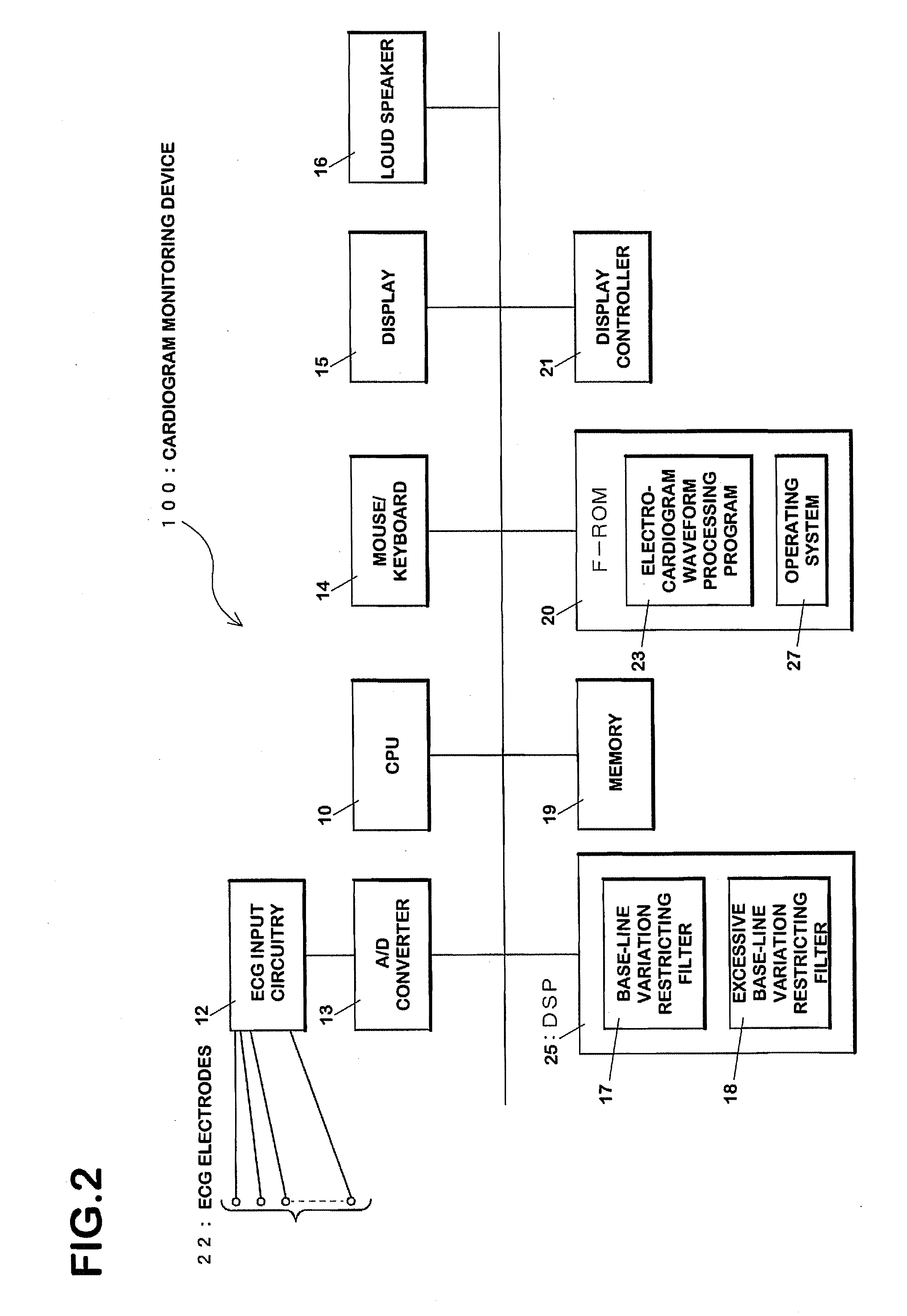
[0147] The CPU 10 of the monitoring device 100 measures cardiac voltages of an examinee via the ECG electrodes 22 (FIG. 12, step S500). The measured voltage signals become cardiogram waveform data upon execution of amplification processing and saturation restriction processing (S501) by the ECG input circuitry 12 and of A / D conversion processing by the A / D converter 13 (S503). Such cardiogram waveform data is recorded on the memory 19.

[0148] Subsequently, the CPU 10 reads out the cardiogram waveform data recorded on the memory 19 and recognizes the feature values for cardiogram waveforms represented by the cardiogram waveform data (S505).

[0149] In particular, the CP...

second embodiment

5. Second Embodiment

5-1. Program Flowchart

[0188]FIGS. 17 and 18 are flowcharts of a cardiogram display processing program according to the second embodiment. In the second embodiment, the CPU 10 generates base-line variation restriction data in accordance with cardiogram waveform data, and generates excessive base-line variation restriction data only to a portion where variation of a baseline is notable. In this regard, this embodiment differs from the first embodiment in which the base-line variation restriction data and the excessive base-line variation restriction data are generated for cardiogram waveform data during the period of start measuring cardiogram to finish measuring thereof. Although, display is carried out in a real-time basis in the first embodiment, cardiogram waveform data is stored once and is read out for recognition and display in the second embodiment. Needless to say, it is possible to carry out real-time display in the second embodiment.

[0189] A flowchart...

third embodiment

7. Third Embodiment

[0201] In the first and second embodiments, determination of using any one of the filters is made in accordance with waveform values at the feature points. Determination of using any one of the filters is made in accordance with comparison values among waveform data after filtering in the third embodiment. In other words, the third embodiment uses the comparison values among the waveform data after filtering as the feature values representing base-line variation.

[0202] Hardware structure in the third embodiment is similar to that shown in FIG. 2. As shown in FIG. 21, the first base-line variation restricting filter 17a, the second base-line variation restricting filter 17b, the third base-line variation restricting filter 17c and the fourth base-line variation restricting filter 17d are formed by the DSP 25. These filters have the basically the same structure as that shown in FIGS. 5 and 6. In this embodiment, a low cut-off frequency for the first base-line varia...


PUM


Abstract

The present invention provides a cardiogram waveform correcting and displaying device capable of facilitating visibility of cardiogram waveforms. A first filtering means 58-1 through n th filtering means 58-n are low-cut filters, each having a first cutoff frequency fc1 through an n th cutoff frequency fcn respectively. Recognition means 56 recognizes feature values of waveforms related to variation of the waveforms in accordance with any outputs of the first filtering means 58-1 through the n th filtering means 58-n. Judging means 62 selects which of the first through the n th filter is used based on the recognized feature values with the recognition means 56. A filter which restricts base-line variation is used when the base-line variation is large, and a filter having less influence to waveforms is used when the base-line variation is small. Display control means 64 displays on a display portion 65 output of the selected filter.

Description

CROSS-REFERENCE TO RELATED APPLICATIONS [0001] All the content disclosed in Japanese Patent Application No. 2004-370908 (filed on Dec. 22, 2004) and Japanese Patent Application No. 2005-186844 (filed on Jun. 27, 2005) including specification, claims, drawings and abstract and summary is incorporated herein by reference in its entirety. FIELD OF THE INVENTION [0002] The present invention relates to a cardiogram waveform correcting and displaying device and a method of correcting and displaying cardiogram waveforms. Specifically, the present invention relates to one increasing visibility of cardiogram. BACKGROUND ART [0003] In order to make an appropriate diagnosis on cardiac function of a patient, display continuity for cardiogram waveforms is required for a device for displaying cardiogram waveforms. For example, such continuity can not be maintained when the base-line of cardiogram varies greatly by noises such as body movement of an examinee. There exists a technology for maintain...

Claims


Application Information

Patent Timeline
IPC IPC(8): A61B5/0402A61B5/308
CPCA61B5/04017A61B5/044A61B5/0428A61B5/0402A61B5/316A61B5/30A61B5/339A61B5/318
Inventor NAGAI, RYUJINAGATA, SHINYA
Owner NIHON KOHDEN CORP
Why Eureka
Try Eureka