
Wear Assembly and Components Thereof, Which is Intended for Machines That Are Used to Move Mateials Such as Earth and Stones

a technology of a mateial machine and a wear assembly, applied in the field of wear, can solve the problems of the use life of the coupling itself, and achieve the effects of preventing the use of complex equipment, reducing the use of tools, and simple replacement operations

Active Publication Date: 2008-02-07
METALOGENIA SA
View PDF36 Cites 106 Cited by
  • Summary
  • Abstract
  • Description
  • Claims
  • Application Information

AI Technical Summary

Benefits of technology

[0015]This means that once the bucket is prepared in the shop, all the members subjected to the wear action can be replaced by other new members at the work site, which may be a quarry face located far from maintenance shops, without needing to use blow torches, welding or specialized personnel. To that end, all the mentioned components can be fixed with interlocking members and pins so that the replacement operations are simple, using few tools and preventing the use of complex equipment.

Problems solved by technology

The excavator tooth couplings must comply with the following features:a) they must withstand mechanical stresses from the transmission of forces from the bucket-tooth bar-tooth assembly with the ground;b) the useful life of the coupling itself is limited due to phenomena of:plastic deformation of the material due to the reactions for counteracting the exerted forces;fatigue: it is calculated that a tooth with normal duration performs more than 50,000 work cycles; because of this, the coupling must be designed to prevent defects occurring due to fatigue phenomena such as cracks or others;wear, being necessary to distinguish two types of wear:1. external wear of the parts due to the flux of the material;2. internal wear due to the fine materials which are introduced between the two members (tooth-tooth bar) and an abrasive effect with the movements between the two parts that occurs, which wears the members.

Method used


Image

  • Wear Assembly and Components Thereof, Which is Intended for Machines That Are Used to Move Mateials Such as Earth and Stones
  • Wear Assembly and Components Thereof, Which is Intended for Machines That Are Used to Move Mateials Such as Earth and Stones
  • Wear Assembly and Components Thereof, Which is Intended for Machines That Are Used to Move Mateials Such as Earth and Stones

Examples


Embodiment Construction

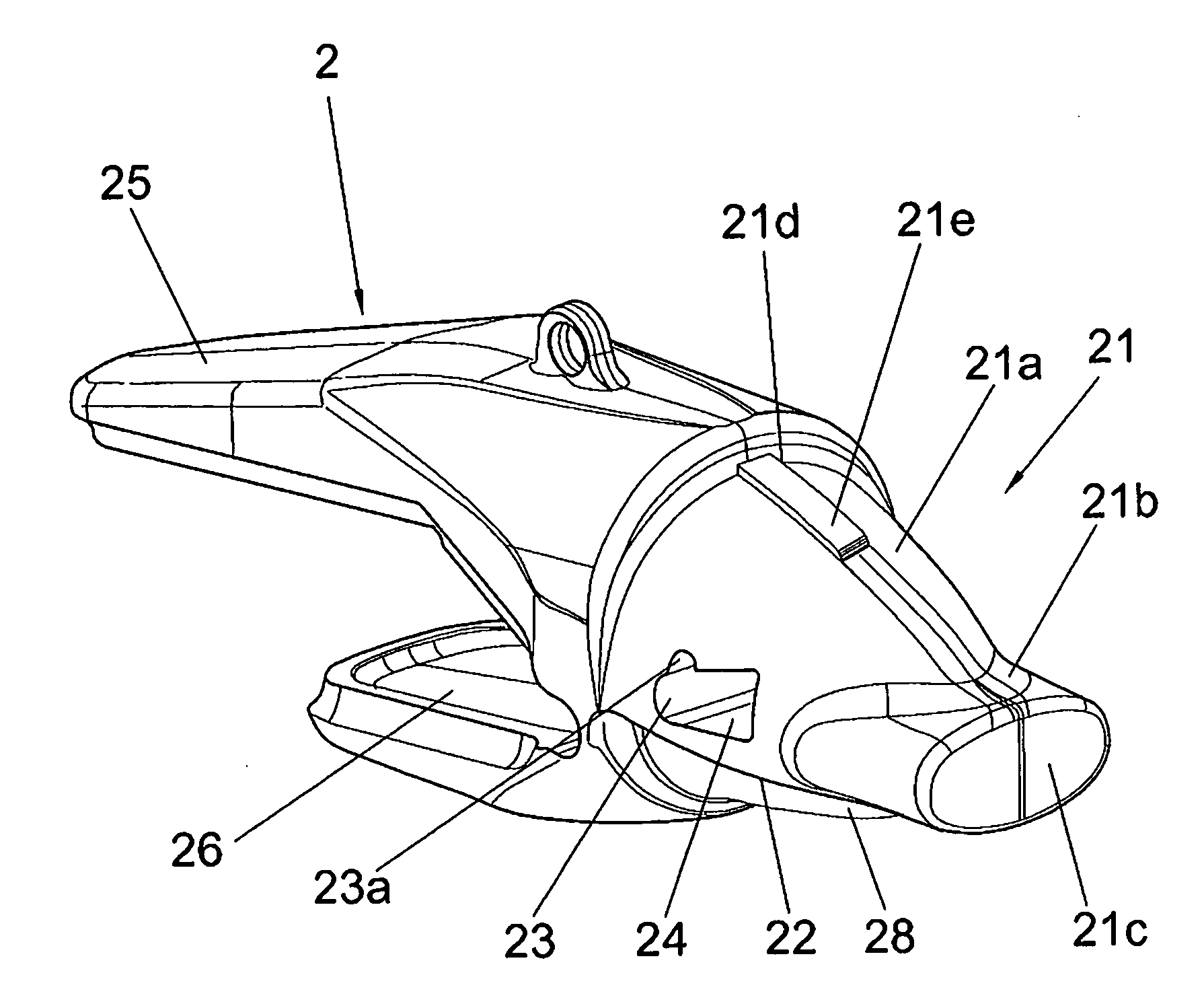
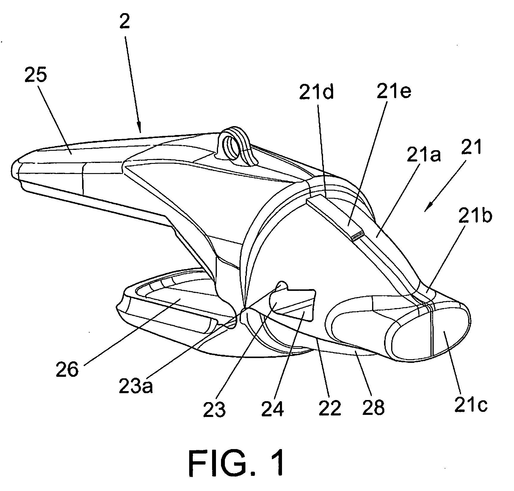
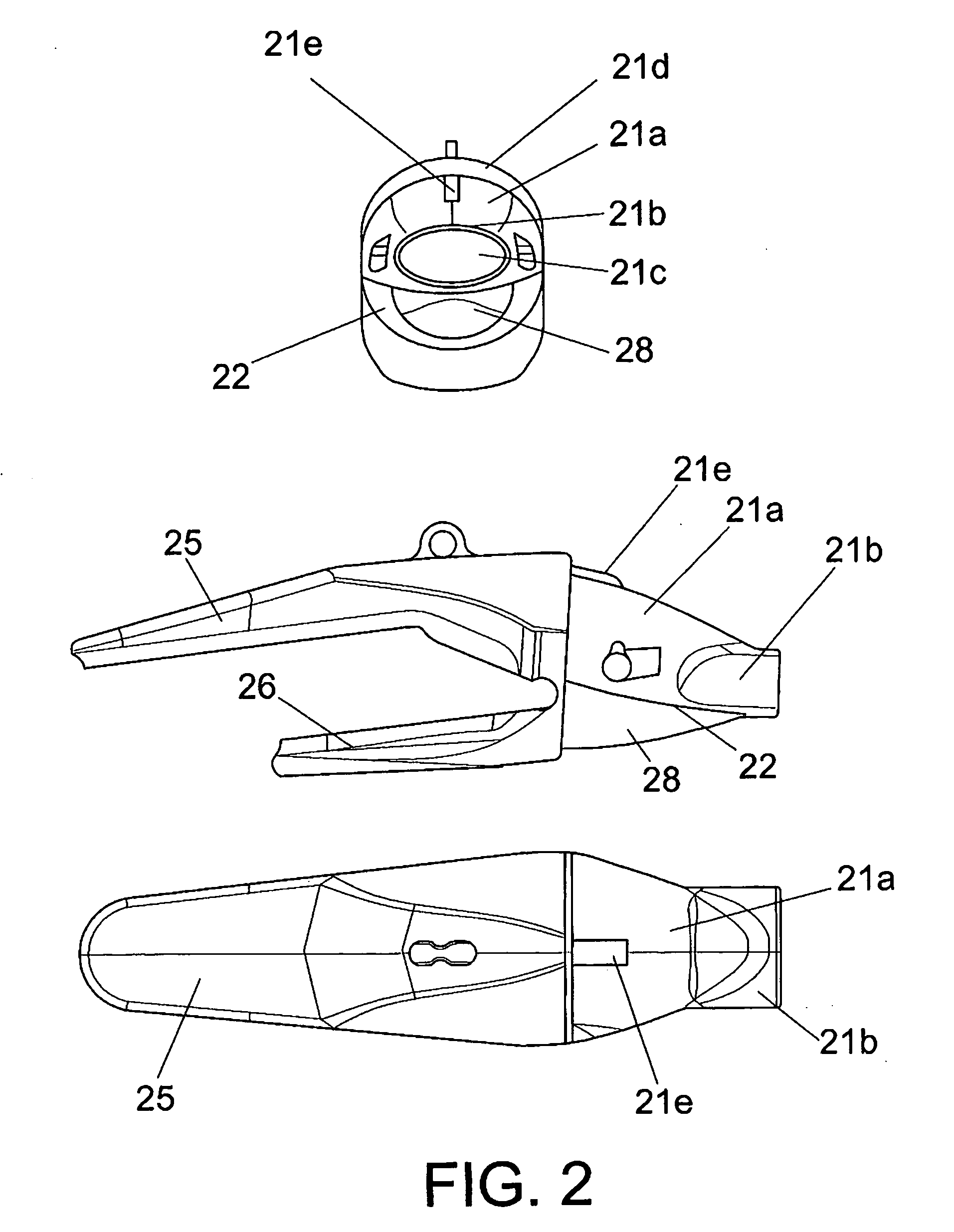
[0076]The wear assembly object of the present invention is made up of a wear member or tooth 1, an adaptor member or tooth bar 2 and a pin 3, 6, which is housed in an opening 23, either a through opening or not, of the tooth bar 2 and coinciding with the at least one through opening 13 of the tooth 1.

[0077]The tooth bar 2 applicable to a machine for moving materials such as earth and stones according to the present invention comprises a body 20 and a projecting area or nose 21, preferably symmetrical with respect to the vertical axis of the coupling or wear assembly, projecting from the front portion to be housed in a hollow, cavity or open box 11 of the tooth, and at least one passage 23, preferably a through passage, for the housing of a pin. Said body 20 of the tooth bar 2 has fixing means 25, 26 in its lower portion for its more or less permanent fixing to the blade of the bucket of a machine for moving earth and the like.

[0078]Said nose 21 of the tooth bar 2 has a proximal port...


PUM


Abstract

The present invention relates to a wear assembly, as well as to the different components thereof, which comprises a wear member or tooth and an adaptor member or tooth bar for wear applications in a machine for moving materials such as earth and stones.The invention contemplates a wear assembly and particularly a coupling system between the different components to one another by means of a characteristic coupling system and at least one retention system assuring the coupling and anchor between the different components, specifically between the wear member and adaptor, the latter in turn being joined to the blade of a bucket or scoop of a machine for moving materials, such as an excavator or the like.

Description

FIELD OF THE INVENTION[0001]The present invention relates to a wear assembly and to the different components thereof, which comprises a wear member or tooth and adaptor member or tooth bar, for wear applications in a machine for moving materials such as earth and stones,[0002]The invention contemplates a wear assembly and particularly a coupling system between the different components by means of a characteristic coupling system and at least one retention system assuring the coupling and anchoring between the different components, specifically between the wear member and adaptor, the latter in turn being joined to the blade of a front edge of a bucket or scoop of a machine for moving materials, such as an excavator or the like.[0003]The present invention also relates therefore to a wear member or tooth and to an adaptor member or tooth bar forming part of said wear assembly and incorporating respective parts of said mutual coupling and anchoring system.TECHNICAL BACKGROUND[0004]Mach...

Claims


Application Information

Patent Timeline
Patent Type & Authority Applications(United States)
IPC IPC(8): E02F9/28
CPCE02F9/2825Y10T403/7069E02F9/2841E02F9/28E02F9/00
Inventor LOPEZ ALMENDROS, JOSEPEREZ LADO, FRANCESOFERNANDEZ MUNOZ, ROBERTO
Owner METALOGENIA SA
Learn More