Thermal management system with thrust recovery for a gas turbine engine fan nacelle assembly

a technology of gas turbine engine and management system, which is applied in the direction of machines/engines, efficient propulsion technologies, mechanical apparatuses, etc., can solve the problems of relative significant thrust loss of turbofan engines, and achieve the effect of reducing volume and reducing thrust losses

Inactive Publication Date: 2008-02-07
UNITED TECH CORP
View PDF3 Cites 110 Cited by
  • Summary
  • Abstract
  • Description
  • Claims
  • Application Information

AI Technical Summary

Benefits of technology

[0008]Independent operation of the variable exhaust nozzles provide independently controlled airflow from the engine heat exchanger and the generator heat exchanger such that intake air usage for each is minimized while maximum thrust is produced in response to the current generator load and engine heat rejection condition.
[0009]The present invention therefore provides a thermal management system that reduces thrust losses and also reduces the volume required therefor for usage in the more compact spaces in advanced turbofan engines.

Problems solved by technology

These heat exchangers typically may require relatively large cross-sectional area ducts that may result in relatively significant thrust losses from the turbofan engine.

Method used


Image

  • Thermal management system with thrust recovery for a gas turbine engine fan nacelle assembly
  • Thermal management system with thrust recovery for a gas turbine engine fan nacelle assembly
  • Thermal management system with thrust recovery for a gas turbine engine fan nacelle assembly

Examples


Embodiment Construction

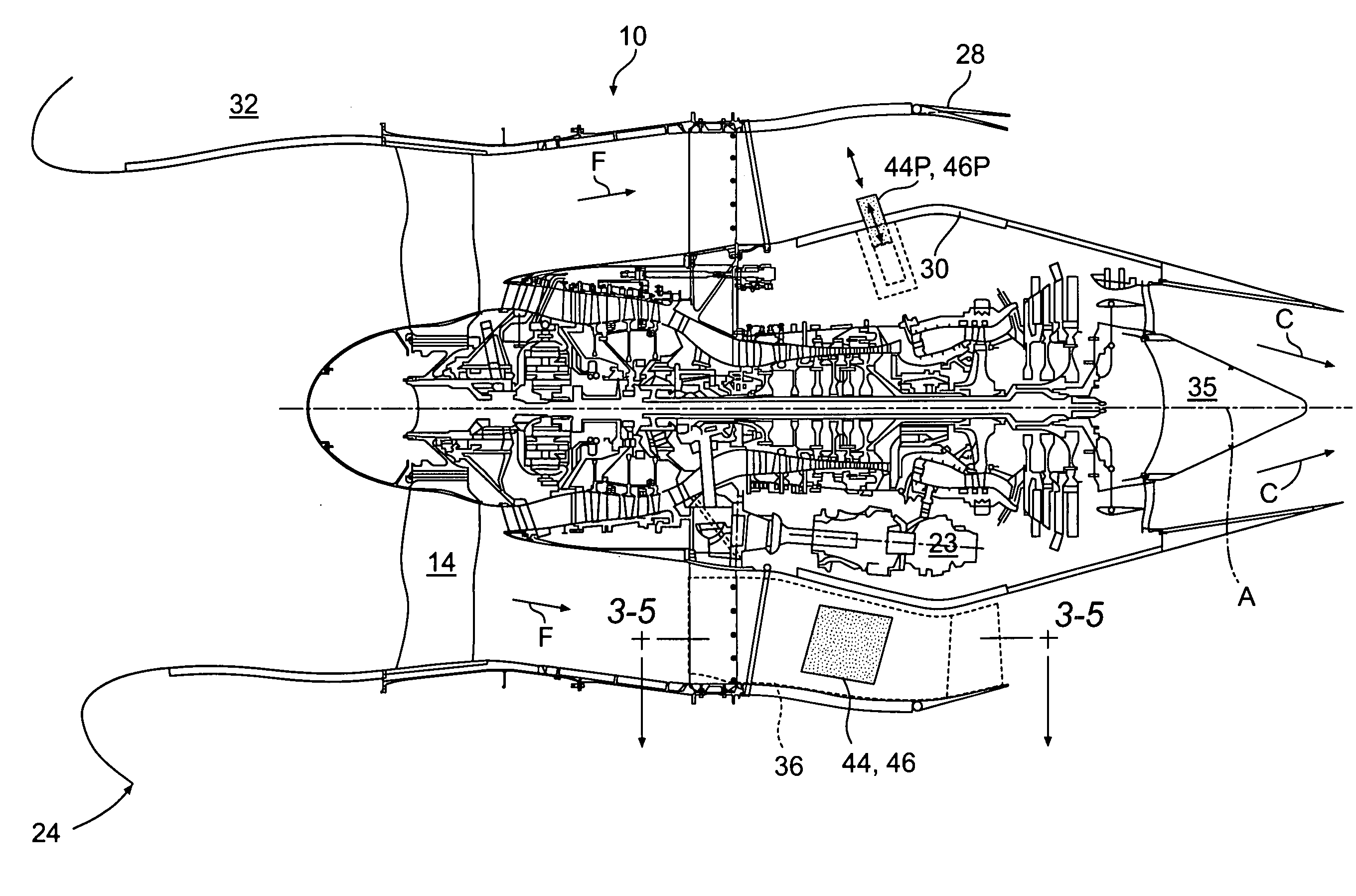
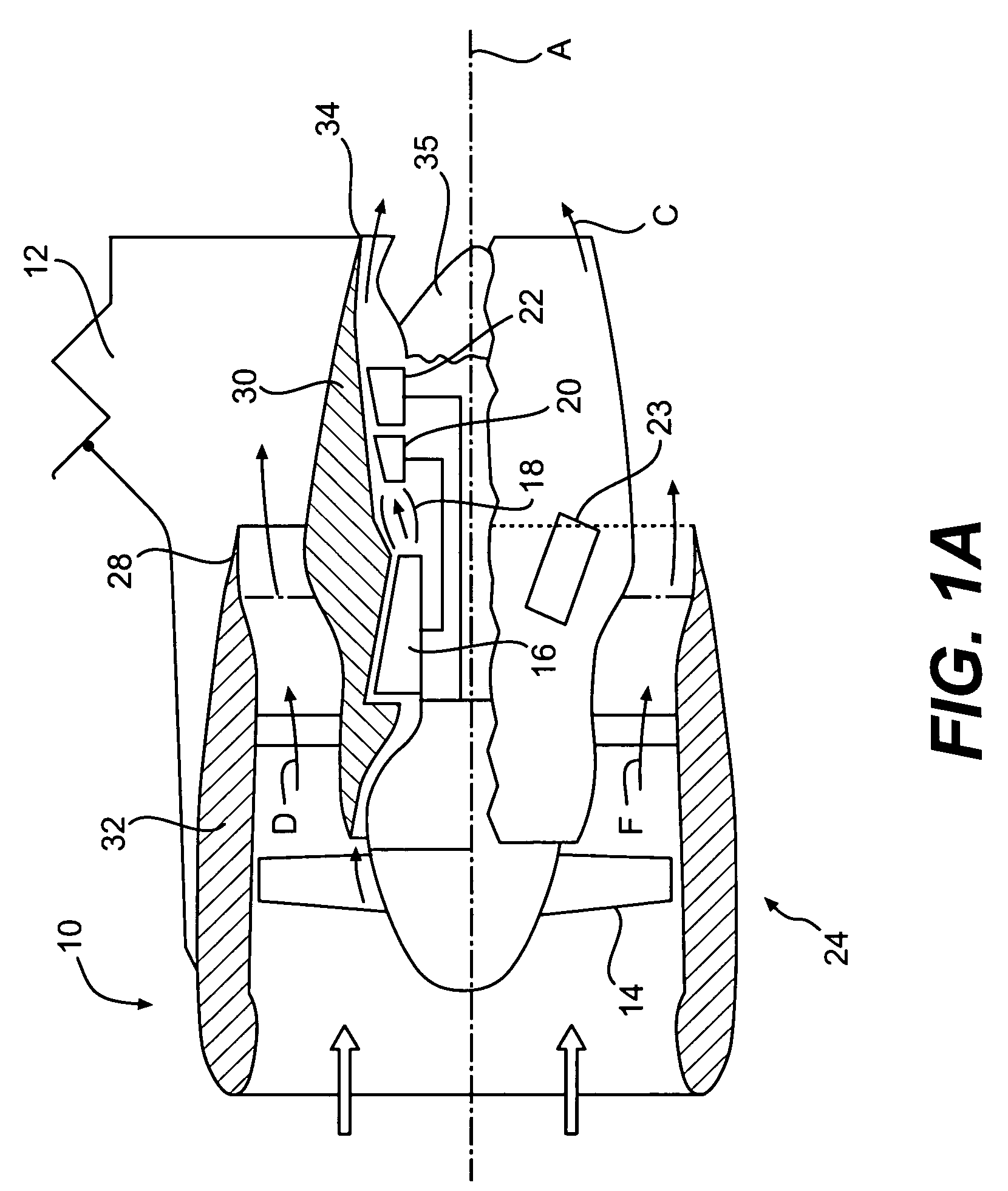
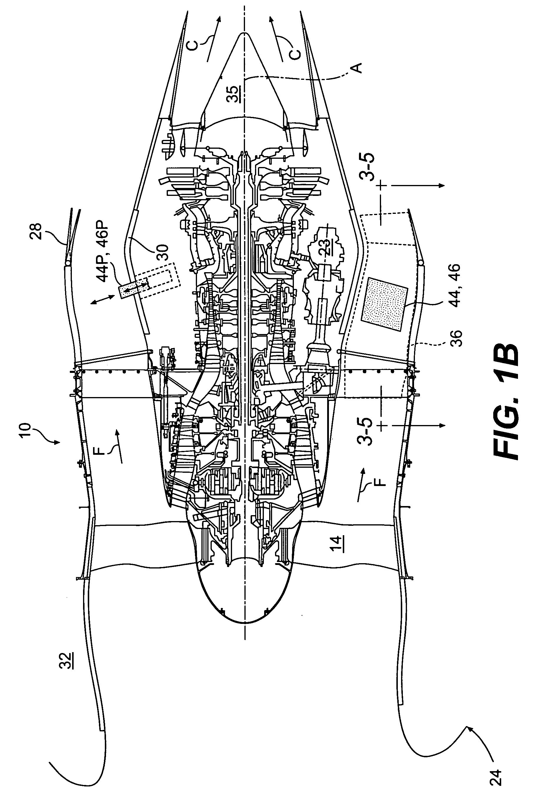
[0019]FIG. 1A illustrates a general partial fragmentary view of a gas turbofan engine 10 suspended from an engine pylon 12 as typical of an aircraft designed for subsonic operation. The engine 10 is preferably a high-bypass turbofan aircraft engine. The engine 10 typically includes in serial flow communication a fan 14 with a low pressure compressor, a high pressure compressor 16, an annular combustor 18, a high pressure turbine 20, and a low pressure turbine 22. Preferably, a generator system 23 is also driven by the engine 10.

[0020]During operation, air is pressurized in the compressor and mixed with fuel in the combustor for generating hot combustion gases which flow through the high and low pressure turbines that extract energy therefrom. The high pressure turbine powers the compressor through a shaft therebetween, and the low pressure turbine powers the fan through another shaft therebetween.

[0021]The exemplary turbofan engine 10 is in the form of a high bypass ratio engine mou...


PUM


Abstract

A thermal management system locates a separate engine heat exchanger and generator heat exchanger into an engine nacelle pylon that is split to provide independent control of both a generator cooling circuit and an engine cooling circuit. A variable exhaust nozzle is provided downstream of each heat exchanger as each has different thermal and heat rejection requirements such that intake air is minimized and maximum thrust is produced in response to the current generator load and engine heat rejection.

Description

BACKGROUND OF THE INVENTION[0001]The present invention relates to a thermal management system for a gas turbine engine, and more particularly to a nacelle pylon split by a bulkhead which provides for independent thermal control of both a generator heat exchanger circuit and an engine heat exchanger circuit as well as utilizing the rejected heat therefrom to increase thrust.[0002]Thermal management systems for a turbofan engine and associated equipment, such as an integrated drive generator, utilize a pressurized lubricant such as an oil, to lubricate, cool and clean the engine main bearings, gear box gears, and the like. During usage, the lubricant receives thermal energy.[0003]The heat of the lubricants in such systems has increased due to the use of larger electrical generators for increased electrical power production and increased usage of geared turbofans with large fan-drive gearboxes.[0004]Thermal management systems typically have a first heat exchanger having passageways thr...

Claims


Application Information

Patent Timeline
Patent Type & Authority Applications(United States)
IPC IPC(8): F02K1/00
CPCF01D15/10F01D25/12F02C7/141F02C7/185F02K1/1207Y02T50/675F02K3/115F05D2220/76F05D2260/213F05D2260/234Y02T50/671F02K3/06Y02T50/60
Inventor SCHWARZ, FREDERICK M.GORBOUNOV, MIKHAIL B.
Owner UNITED TECH CORP
Why Eureka
Try Eureka