Lifting Device having Double Screw Rods

Inactive Publication Date: 2008-02-07
TIMOTION TECH CO LTD
View PDF4 Cites 23 Cited by
  • Summary
  • Abstract
  • Description
  • Claims
  • Application Information

AI Technical Summary

Benefits of technology

[0008]The present invention is to provide a lifting device having double screw rods, in which the parallel arrangement of each screw rod makes it interchangeable, so that the whole structure is simplified to save the expense of machining and heat-treating each member, thereby to efficiently reduce the cost.

Problems solved by technology

Since the total length of the extension of the lifting device does not exceed the sum of two sliding units and the total length of the retraction is not lower than the length of any one longer sliding unit, the extension and retraction stroke that is possibly achieved is limited and thus cannot satisfy the requirement for a larger adjusting space in the existing market.
Thus, it is an important issue for those skilled in this art to provide a lifting device having multiple-stage sliding units.
However, in practical use, the conventional lifting device having screw rods has still some problems as follows.
Since the primary members such as the cylindrical screw rod and the pillared screw rod are manufactured separately, those elements cannot be interchangeable, so that the total cost of the elements cannot be reduced efficiently.
Further, the inside and outside of the cylindrical screw rod are provided with threads, the machining process is thus very complicated and difficult.
Also, after the machining process, it is not easy to perform the heat treatment to obtain a good surface hardness.
As a result, it is very fast to generate wear between the inner threads of the cylindrical screw rod and the pillared screw rod, causing the increase in the subsequent cost for maintenance and inconvenience in use.

Method used


Image

  • Lifting Device having Double Screw Rods
  • Lifting Device having Double Screw Rods
  • Lifting Device having Double Screw Rods

Examples


Embodiment Construction

[0017]The characteristics and the technical contents of the present invention will be described with reference to the following detailed description and the accompanying drawings. However, it should be understood that the drawings are illustrative but not used to limit the scope of the present invention.

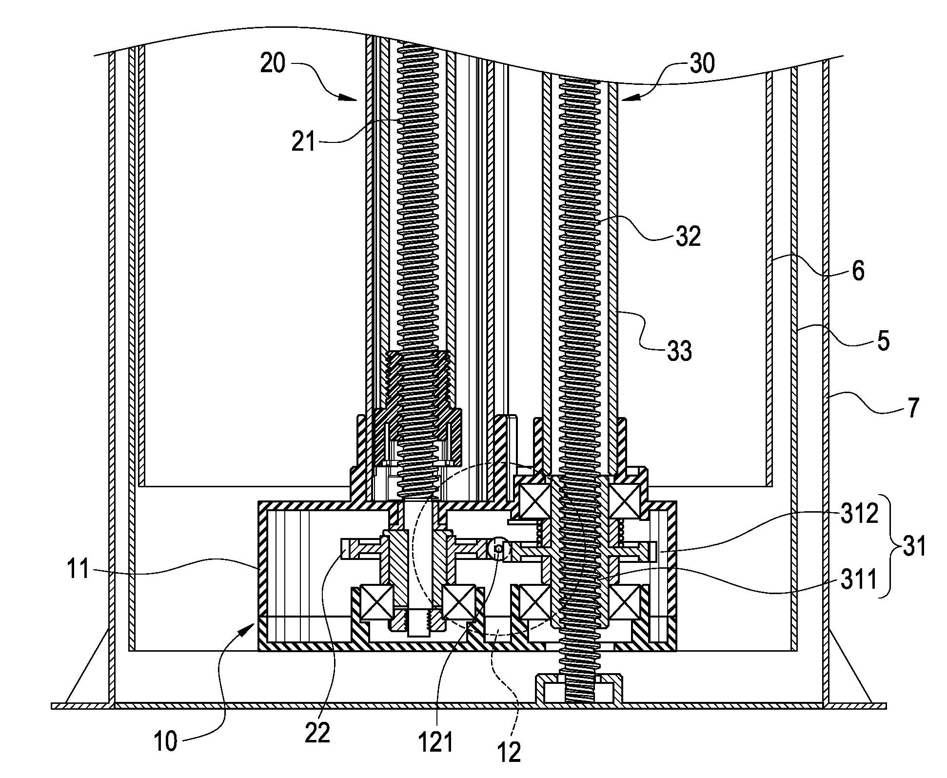
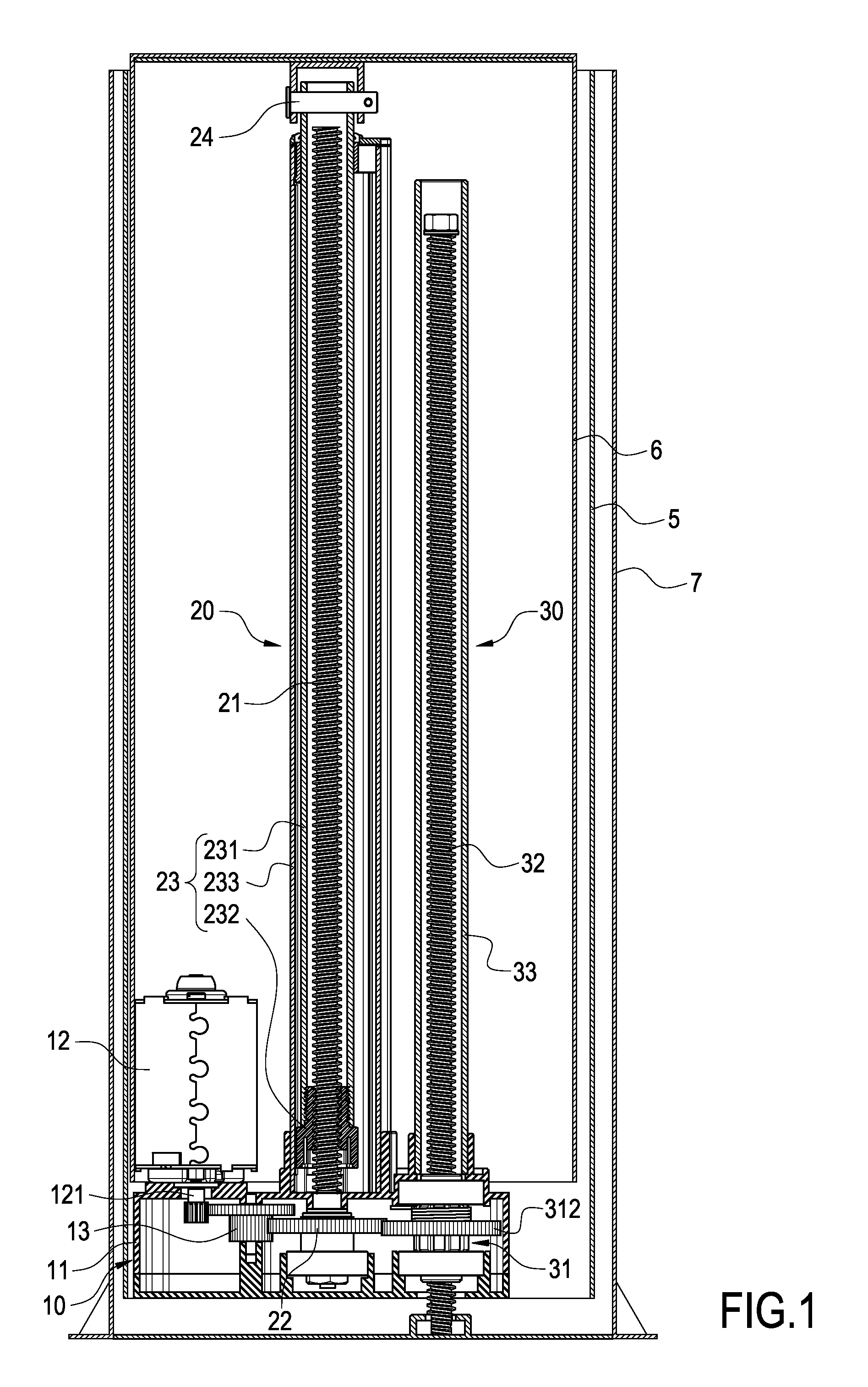
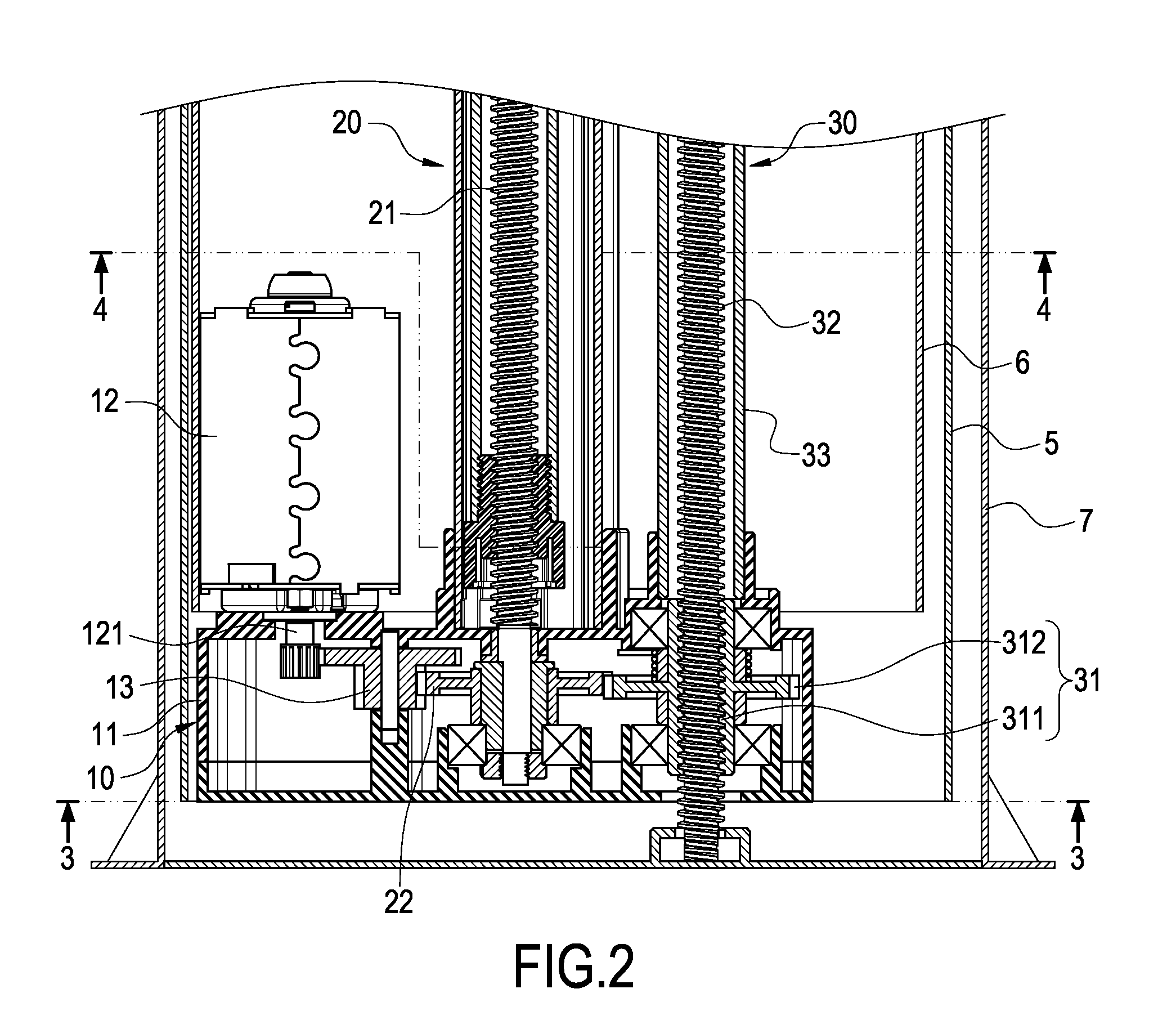
[0018]FIG. 1 is an assembled cross-sectional view of the first embodiment of the present invention. FIG. 2 is a partially enlarged cross-sectional view of the present invention. FIG. 3 is a cross-sectional along the line 3-3 in FIG. 2. FIG. 4 is a cross-sectional along the line 4-4 in FIG. 2. The present invention provides a lifting device having double screw rods. The lifting device is connected respectively to a first sliding unit 5, a second sliding unit 6 and a third sliding unit 7 which are interconnected with each other so as to control the relative sliding movements among each sliding unit 5, 6, 7. Each sliding unit 5, 6, 7 can be formed into a hollow rectangular tube with dif...


PUM


Abstract

A lifting device having double screw rods is respectively connected on first, second and third sliding units interconnected to one another, which includes a driving means, a first transmission means and a second transmission means. The driving means is fixedly connected to the bottom end of the first sliding unit. The first transmission means includes a screw rod connected to the driving means and a telescopic tube assembly linearly movable relative to the screw rod. The screw rod is driven by the driving means. The other end of the telescopic assembly is fixedly connected to the top end of the second sliding unit. The second transmission means is provided at one side of the first transmission means and parallel thereto. Further, the second transmission means comprises a sleeve driven by the first transmission means to rotate and a screw rod threadedly connected to the sleeve. One end of the screw rod is fixedly connected to bottom end of the third transmission means. With the above arrangement, the whole structure is simplified to save the expense of machining and heat-treating each member, thereby to efficiently reduce the cost.

Description

BACKGROUND OF THE INVENTION[0001]1. Field of the Invention[0002]The present invention relates to a lifting device having double screw rods, and in particular to a lifting device mounted in the electric table or electric bed.[0003]2. Description of Prior Art[0004]Conventionally, a lifting device is provided within a two-stage sliding unit and then connected to an electric table or electric bed, so that the higher or lower position of the electric table or electric bed can be adjusted. Since the total length of the extension of the lifting device does not exceed the sum of two sliding units and the total length of the retraction is not lower than the length of any one longer sliding unit, the extension and retraction stroke that is possibly achieved is limited and thus cannot satisfy the requirement for a larger adjusting space in the existing market. Therefore, there is proposed a multiple-stage (such as three-stage or four-stage) sliding unit. In addition to have a larger amount of ...

Claims


Application Information

Patent Timeline
IPC IPC(8): F16H27/02
CPCF16H25/20F16H2025/2059Y10T74/18672F16H25/2056F16H2025/2081
Inventor WANG, CHIA-JUNG
Owner TIMOTION TECH CO LTD
Why Eureka
Try Eureka