
Monostatic Multi-beam Radar Sensor, as Well as Method

a radar sensor and multi-beam technology, applied in the field of monostatic multi-beam radar sensor, can solve the problems and achieve the effect of saving surface space and wiring expens

Inactive Publication Date: 2011-02-10
ROBERT BOSCH GMBH
View PDF29 Cites 3 Cited by
  • Summary
  • Abstract
  • Description
  • Claims
  • Application Information

AI Technical Summary

Benefits of technology

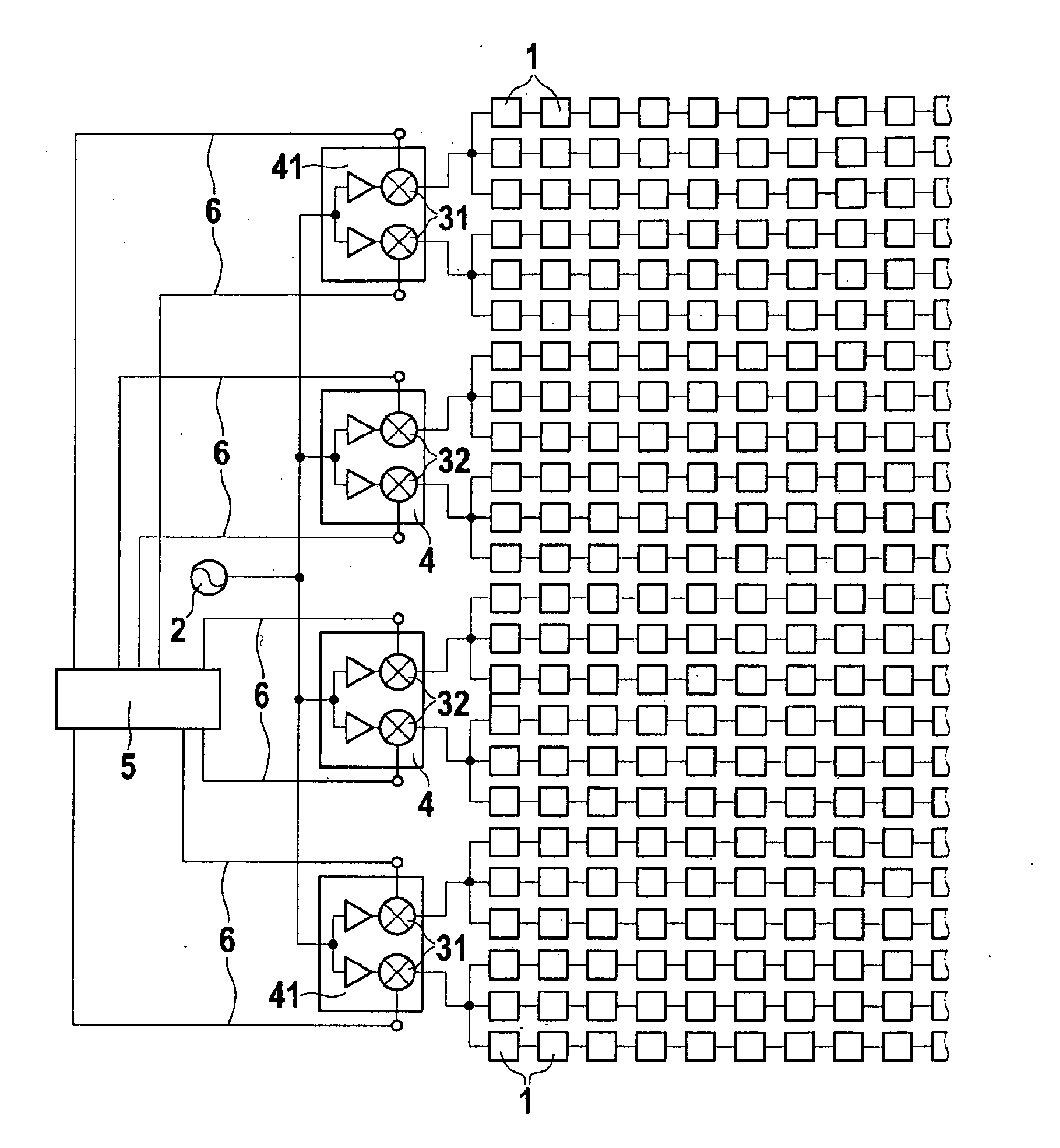
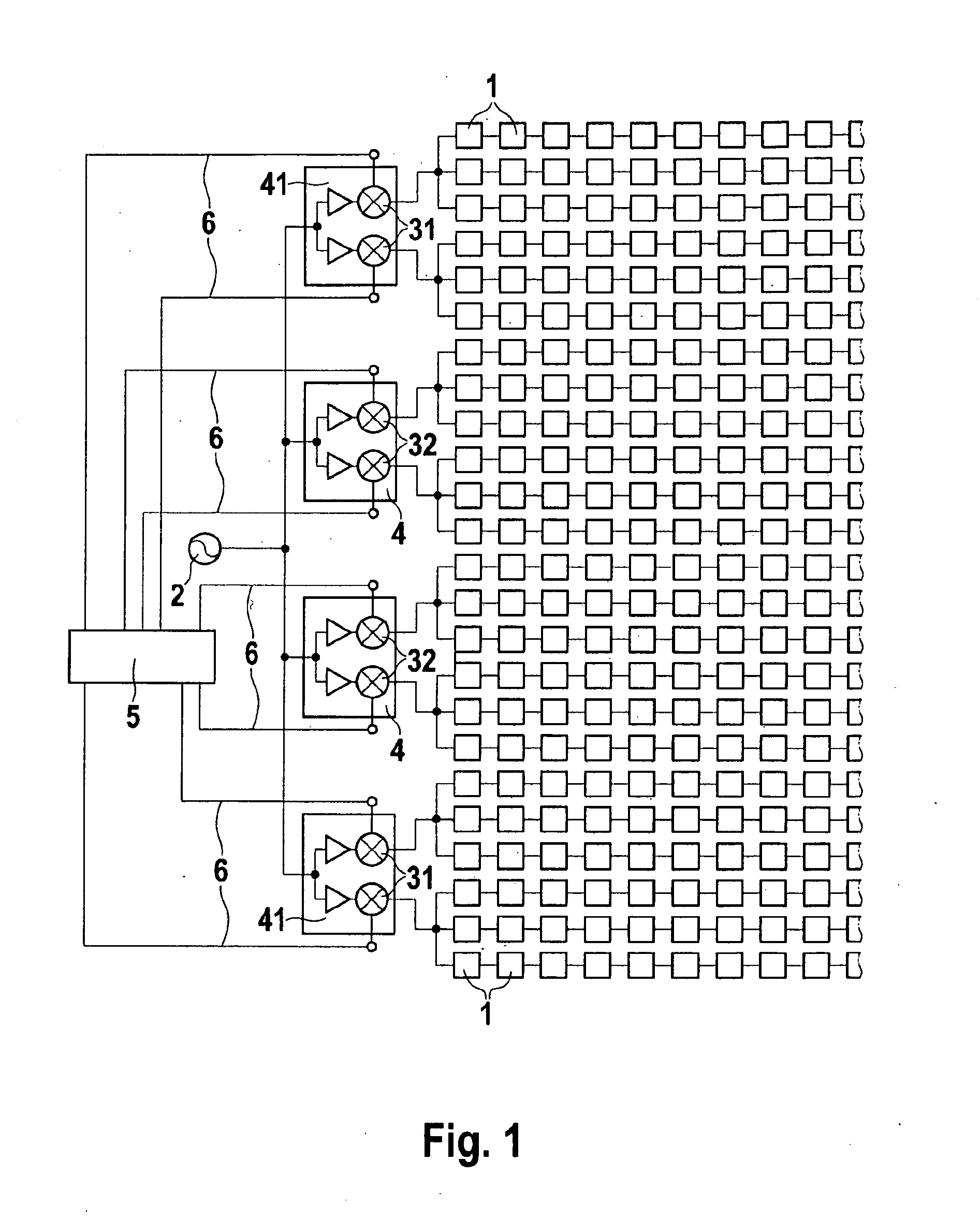
[0006]Using a monostatic multi-beam radar sensor, in which a group antenna is provided and a mixer system made up of a plurality of transfer mixers connected to antenna elements of the group antenna in such a way that a first number of transfer mixers is switched to isolation mode and a second number of the transfer mixers is switched to transfer mode, it is possible to set different directional characteristics for the transmit and receive operation in a monostatic system, i.e., with one shared antenna for transmit and receive operation, while requiring very little space, for instance 50% less antenna area than a bistatic system. The present invention is based on the recognition that transfer mixers switched to isolation mode also supply output signals that are able to be evaluated by phase-correct and amplitude-correct summing in receive operation, so as to achieve digital beam forming (DBF), for instance. In receive operation, the entire antenna aperture is therefore available, and the radiation lobes are correspondingly narrow, which is advantageous for increasing the resolution, especially in lane-relevant regions for LRR (long-range radar). In transmit operation, the full aperture is not available because of the outer, isolating mixers, in particular, and the directional diagram becomes correspondingly broad. The oscillator or transmit signal is able to pass the mixers switched to transfer mode, while it is damped by 25 to 30 dB via the mixers switched to isolation mode and no longer contributes to the directional effect to any significant degree. The aperture is therefore effectively halved, so that the detection range doubles in the transmit case.
[0007]In a matrix-type structure of the group antenna it is advantageous to switch the transfer mixers connected to the outer antenna elements to isolation mode.
[0009]It is advantageous to route a plurality of slots of antenna elements of the matrix-type group antenna to one transfer mixer in each case. This saves space for the transfer mixers without restricting the resolution to any considerable extent. Placing two transfer mixers on one chip in each case, both mixers being switched to isolation or transmit mode, also saves surface space and wiring expense.

Problems solved by technology

Placing two transfer mixers on one chip in each case, both mixers being switched to isolation or transmit mode, also saves surface space and wiring expense.

Method used


Image

  • Monostatic Multi-beam Radar Sensor, as Well as Method
  • Monostatic Multi-beam Radar Sensor, as Well as Method

Examples


Embodiment Construction

[0011]The present invention according to FIG. 1 provides a matrix-type group antenna having antenna elements 1 for the monostatic operation. A high-frequency source 2 of 77 GHz, for example, is connected to antenna elements 1 via mixers 31, 32. In the exemplary embodiment shown, three slots of antenna elements 1 are combined in each case and connected to a mixer 31 or 32. Mixers 31 or 32 may be implemented as MMICs. Two mixers 31 and 32 are situated together on one chip 4 or 41 in each case. In order to generate a different directivity characteristic for the transmit operation than for the receive operation, the outer two mixers 31 on chip 41 are switched to isolation mode, and the four inner mixers 32 on chip 4 are switched to transfer mode.

[0012]In receive operation, an isolating and a transferring mixer both supply identical output signals. If a directivity pattern is produced by digital beam forming (in-phase and amplitude-correct summing of the eight output signals) then the en...


PUM


Abstract

A monostatic multi-beam radar sensor includes a group antenna and a mixer system made up of a plurality of transfer mixers connected to antenna elements of the group antenna. A first number of the transfer mixers is switched to isolation mode and a second number of the transfer mixers is switched to transfer mode in order to realize different directional characteristics for the transmit and receive operation.

Description

BACKGROUND OF THE INVENTION[0001]1. Field of the Invention[0002]The present invention relates to a monostatic multi-beam radar sensor and a method for operating such a radar sensor.[0003]2. Description of Related Art[0004]A monostatic multi-beam radar sensor for motor vehicles is known from published international patent application WO 2006 / 029926 A1, the sensor being made up of a group antenna, a planar lens having a plurality of inputs, and a homodyne mixer system having a plurality of transfer mixers, which are connected in parallel to the inputs of the lens. The lens causes beam bundling both in transmit and in receive operation. The use of such a radar sensor enables parallel processing of the signals from a plurality of radar beams. The transfer mixers can be placed in a tight space on one board.[0005]In various applications, e.g., in ACC (adaptive cruise control), the transmit and receive characteristics must differ. This has previously been achieved with the aid of bi-static...

Claims


Application Information

Patent Timeline
Patent Type & Authority Applications(United States)
IPC IPC(8): H01Q3/12
CPCG01S7/032H01Q25/002G01S2013/9375G01S7/036G01S2013/93271
Inventor BINZER, THOMASSTEINBUCH, DIRK
Owner ROBERT BOSCH GMBH
Learn More