System and method for casting and rolling metal

a technology of metal casting and metal rolling, applied in the field of installation and a method of casting and rolling metal, can solve the problems of space, energy, and expense, and achieve the effects of high aluminum content, rapid solidification, and better utilization of rolling trains

Inactive Publication Date: 2012-01-12
SMS DEMAG AG
View PDF8 Cites 5 Cited by
  • Summary
  • Abstract
  • Description
  • Claims
  • Application Information

AI Technical Summary

Benefits of technology

[0009]The installation in accordance with the invention allows better utilization of a rolling train. In addition, an existing rolling train can be better utilized by expansion with additional casting lines. In addition, the provision of a horizontal thin-slab casting installation makes it possible to produce high alloy or super alloy steels, including, for example, crack-sensitive steels and especially steels with a high aluminum content, since the thin slabs do not come into contact with casting flux in the horizontal thin-slab casting installation as a result of the traveling mold or conveyor belt. As a result of the combination with the horizontal thin-slab casting installation, a fine grain structure is also realized due to rapid solidification and a low segregation tendency. Furthermore, oscillation marks on the cast product can be avoided by a traveling mold. Possible cracking, bending or straightening damage is also avoided. In addition, standard steels can also be produced by the additionally provided thin-slab casting installation. All together, the production program or spectrum is thus considerably expanded compared to known installations. The use of thin-slab technology also makes it possible directly to produce strips with a thickness of less than 15 mm, which greatly reduces the rolling work in the rolling train.
[0010]In a preferred embodiment of the installation, each of the two or more casting lines is designed as a horizontal thin-slab casting installation, which is followed by the rolling train for rolling the slabs cast in the horizontal thin-slab casting installations. With this type of arrangement, even an installation that comprises only horizontal thin-slab casting installations can be operated in a cost-efficient way.
[0011]In another preferred embodiment of the installation, the two or more casting lines are designed in a way that makes it possible to cast slabs of such small thickness that a roughing stand is not necessary for rolling the cast slabs before they enter the rolling train. This type of arrangement saves space, energy, and expense.

Problems solved by technology

This type of arrangement saves space, energy, and expense.

Method used


Image

  • System and method for casting and rolling metal
  • System and method for casting and rolling metal
  • System and method for casting and rolling metal

Examples


Embodiment Construction

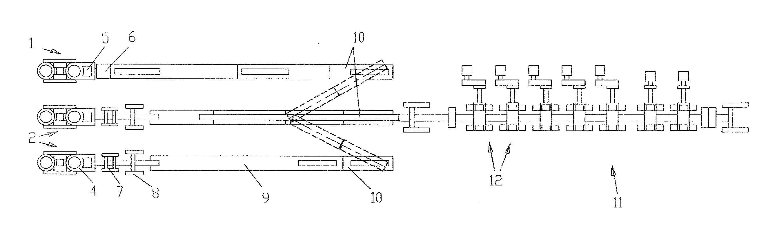
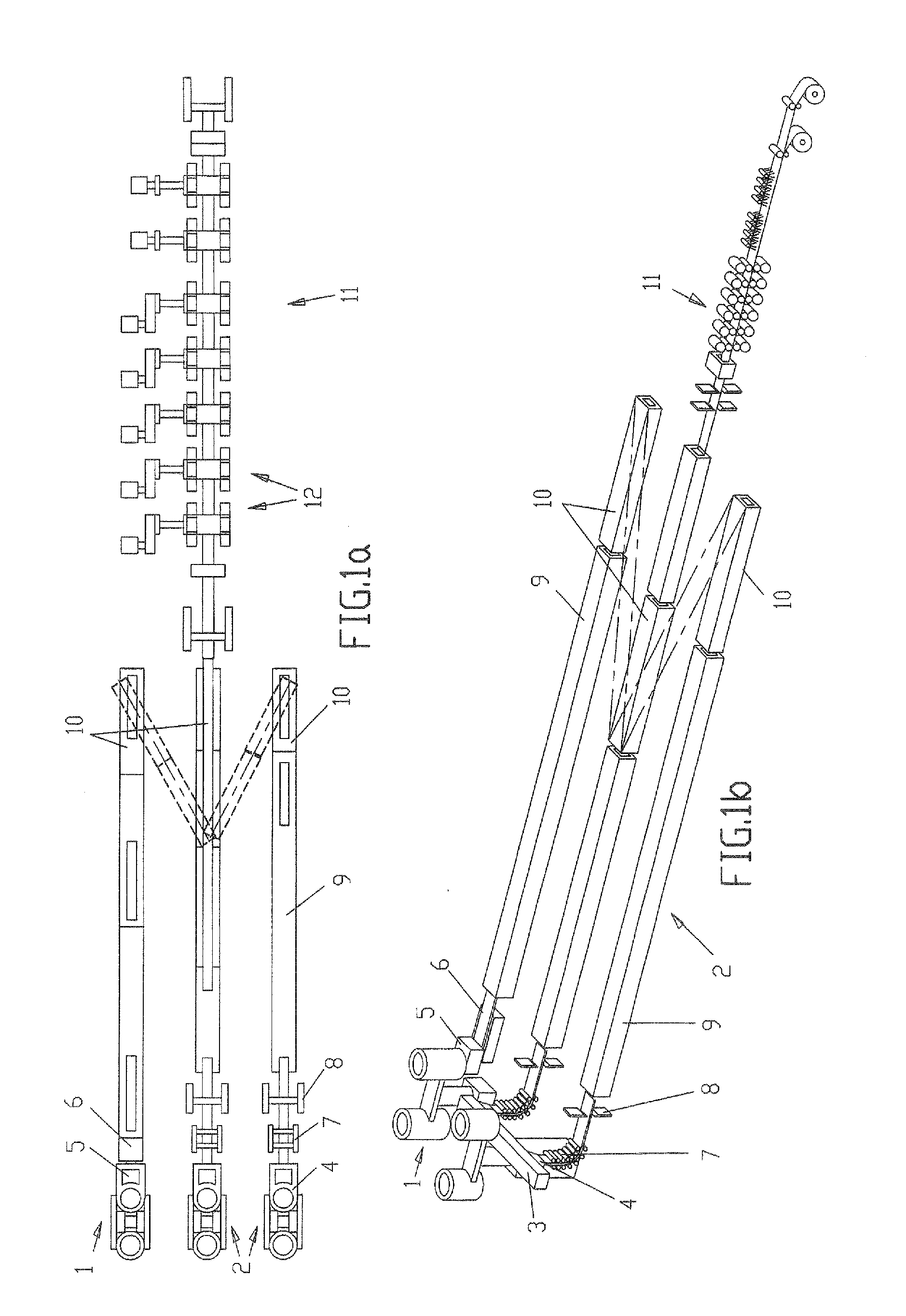
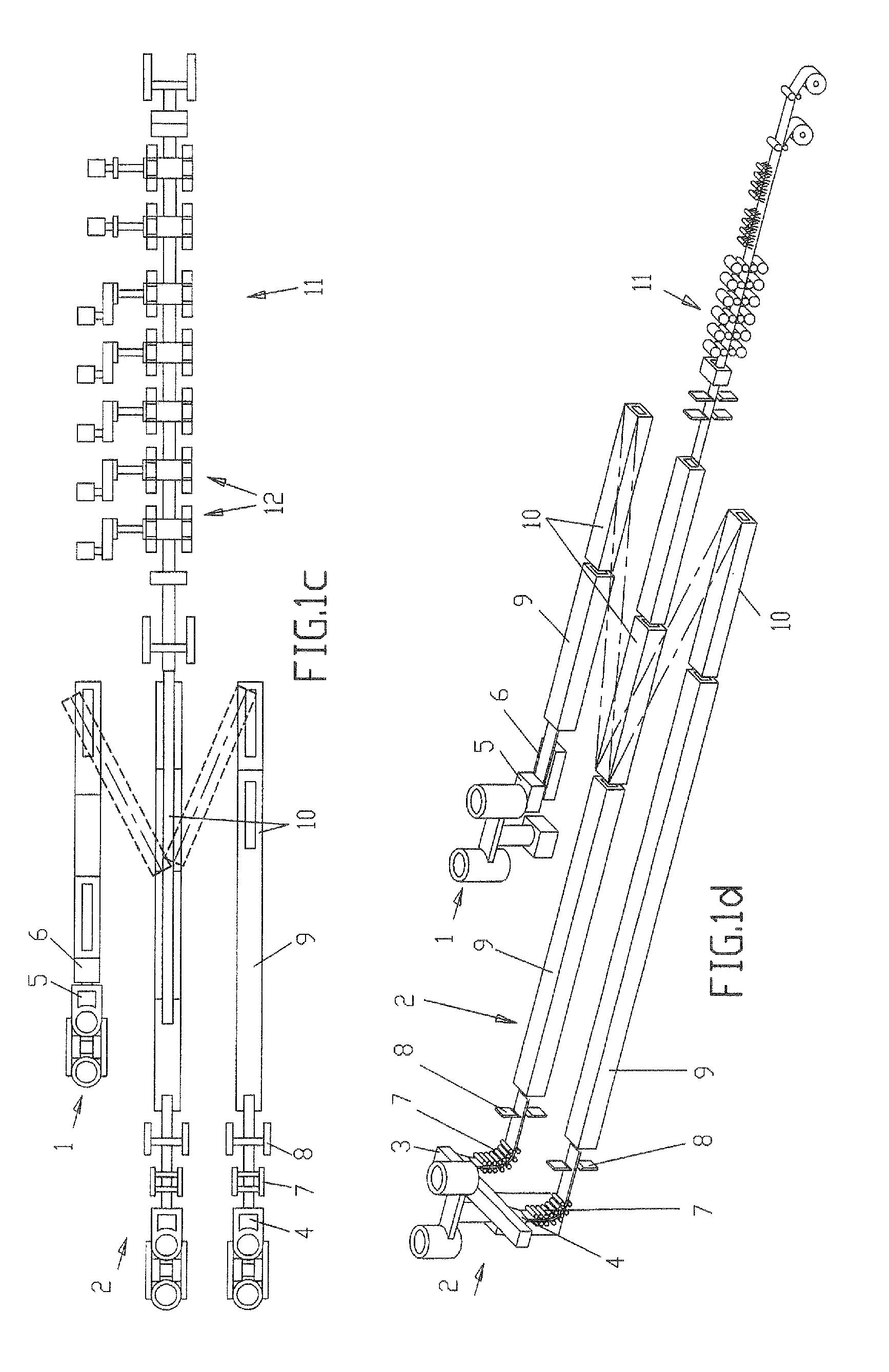
[0033]FIG. 1a shows a specific embodiment of an installation of the invention with two CSP installations 2 or vertical thin-slab casting installations 2. These vertical thin-slab casting installations 2 in themselves are already well known. In these installations 2, a strand is first vertically cast with a mold 4 and then bent by a bending device 7 and subsequently straightened with a straightening unit. Optionally, a cutting unit 8 or shears 8 are provided farther along in the direction of casting. The slabs then arrive in a downstream temperature-adjusting unit 9, especially a furnace 9, where, for example, they can be heated or held at a certain temperature.

[0034]A horizontal thin-slab casting installation 1 is arranged alongside the two CSP casting installations 2. This installation is preferably located parallel next to one of the vertical thin-slab casting installations 2. The installation 1, which is shown at the top in FIG. 1a, has a charging vessel 5 for the melt and a conv...


PUM

PropertyMeasurementUnit
thicknessaaaaaaaaaa
thicknessaaaaaaaaaa
thicknessaaaaaaaaaa

Abstract

The invention essentially relates to a device and a method for casting and rolling metal, wherein at least one first and one second casting line for casting slabs and a rolling train for rolling the casted slabs are provided. The first casting line is designed as a horizontal thin-slab casting system (1) which comprises at least one dispensing vessel (5) for a melt and a conveyor belt (6) running horizontally downstream of the at least one dispensing vessel (5) in the casting direction. The second casting system is likewise designed as a horizontal thin-slab casting system (1) and/or as a vertical thin-slab casting system (2), which comprises at least one mold (4) for vertically casting slabs and a bending and straightening device (7) for bending and straightening the vertically casted slabs into a horizontal position. A rolling train (11) for rolling the casted slabs lies downstream of the at least two casting lines, and the at least two casting lines are designed such that the slabs, each of which is cast using one of the at least two casting lines, can be conveyed to the rolling train (11).

Description

FIELD OF THE INVENTION[0001]The invention concerns an installation and a method for casting and rolling metal, especially steel, by means of casting installations and a downstream rolling train.[0002]For the sake of clarity, we shall first define a few terms that are used synonymously in the context of the present specification. The terms “thin slabs” and “slabs” each refer to very thin slabs (5-35 mm thick), thin slabs (35-90 mm thick), medium-thickness slabs (90-150 mm thick), or near-net strip (20-50 mm thick).[0003]In the context of the present specification, the term “horizontal thin-slab casting installation” is synonymous with a horizontal strip casting installation, especially a BCT installation (belt casting technology) or a DSC installation (direct strip casting).[0004]In the context of the present specification, the term “vertical thin-slab casting installation” covers especially the following types of installations: a thin-slab casting installation in accordance with com...

Claims


Application Information

Patent Timeline
Patent Type & Authority Applications(United States)
IPC IPC(8): B22D23/00B22D45/00B22D47/00
CPCB21B1/46B21B39/18B22D11/041B22D11/043B22D11/147B22D11/0631B22D11/141B22D11/142B22D11/143B22D11/045
Inventor BAUSCH, JORGFISCHER, LOTHAR
Owner SMS DEMAG AG
Why Eureka
Try Eureka