
Coated roller

a roller and coating technology, applied in the direction of printing equipment, press sections, manufacturing tools, etc., can solve the problems of reducing the quality of the roller covering, and achieve the effects of reducing scrap, quick curing of materials, and removing the roller quickly and with little expens

Inactive Publication Date: 2008-02-07
SANOFI AVENTIS SA
View PDF28 Cites 0 Cited by
  • Summary
  • Abstract
  • Description
  • Claims
  • Application Information

AI Technical Summary

Benefits of technology

[0007] In this manner, the two components can be mixed with very high energy and quite quickly without air or any other gas being brought into the mixture that would have to be either removed or remain entrapped, thus reducing the quality of the roller covering. The mixing time can be shortened more specifically through the higher mixing energies such as a higher stirring speed, so that, with curing mixtures in particular, the working time for the actual application at the same degree of mixing increases, with the quality of the covering being accordingly enhanced.
[0035] The head is preferably non-destructively removable so that it can be removed from the roller quickly and with little expense once the coating process is completed; in this context, the term “non-destructive” explicitly does not refer to the applied roller covering. It is understood that such a coating process including an attached and removable head and a corresponding coating apparatus are advantageous also irrespective of the other features of the present invention. The same applies to a coated roller the coating of which corresponds on at least one side, as far as its average quality is concerned, to the average quality of the remainder of the covering, this being realizable, according to present knowledge, with such a head only.

Problems solved by technology

In this manner, the two components can be mixed with very high energy and quite quickly without air or any other gas being brought into the mixture that would have to be either removed or remain entrapped, thus reducing the quality of the roller covering.

Method used


Image

  • Coated roller
  • Coated roller
  • Coated roller

Examples


Embodiment Construction

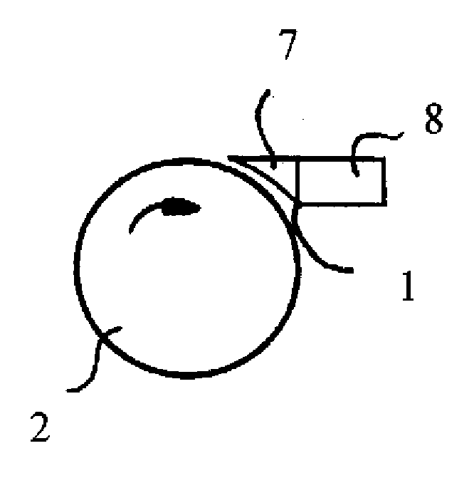
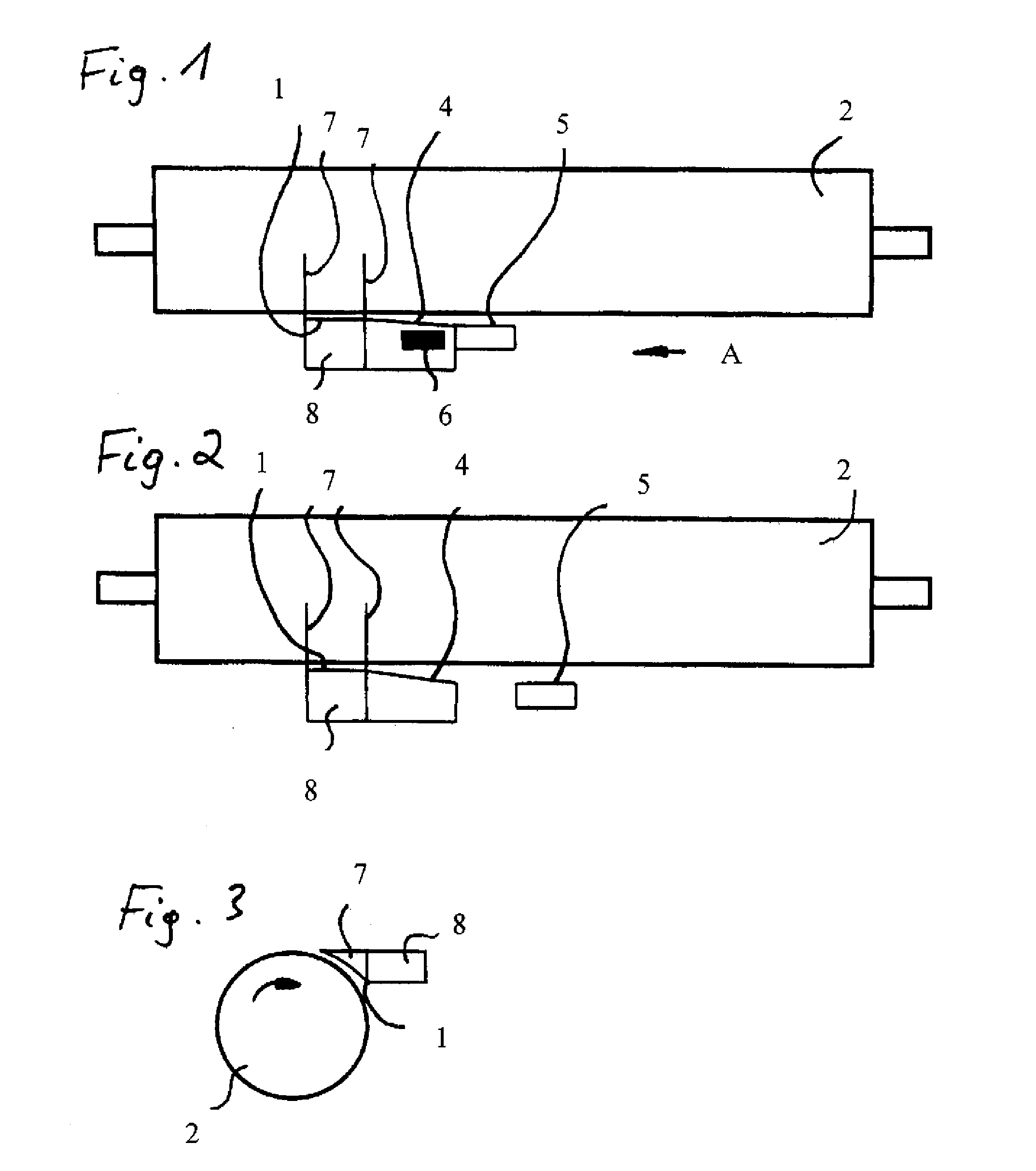
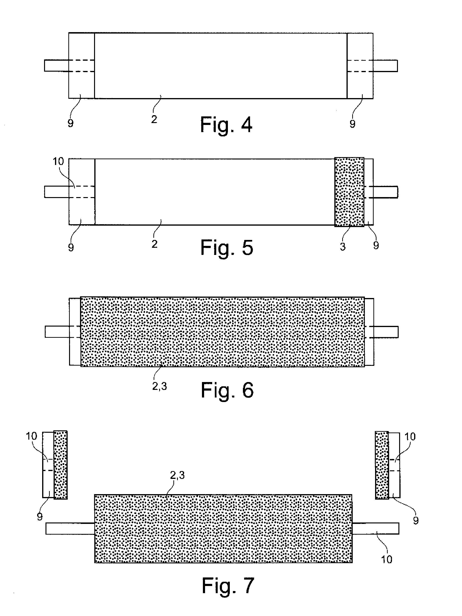
[0045] The coating apparatus illustrated in the FIGS. 1 through 3 each include one application blade 1 that is caused to move along a roller 2 in the direction pursuant to arrow A (see FIG. 1) in order to coat said roller with a liquid but curing coating 3 (see FIGS. 5 through 6).

[0046] The coating apparatus includes a wiping blade 4 trailing behind the application blade 1 and a smoothing blade 5 trailing behind the application blade 1, said blades being displaced accordingly. The smoothing blade 5 can be caused to move together with the application blade 1 (see embodiment according to FIG. 1) or independent therefrom (see embodiment according to FIG. 2). According to need, alternative embodiments may forgo the use of the smoothing blade or the wiping blade.

[0047] The trailing wiping blade 4 thereby permits on the one side to remove excess coating material and to spread it over other regions with less material. Excess material may moreover also be carried away, an overflow 6 being...


PUM


Abstract

A roller has a coating comprised of a plastic matrix of plastic material, wherein the plastic material is a resin. The surface of the coating has less than 50 pores per m2, and hard material particles are embedded in the plastic matrix

Description

CROSS-REFERENCES TO RELATED APPLICATIONS [0001] This application is a continuation of prior filed copending U.S. application Ser. No. 11 / 246,011, filed Oct. 7, 2005, the priority of which is hereby claimed under 35 U.S.C. §120, and which is a continuation of prior International Application Number PCT / DE2004 / 000759, filed on Apr. 13, 2004, which claims the priority of German Patent Applications, Serial Nos. 103 17 025.1, filed Apr. 11, 2003; 103 17 840.6, filed Apr. 16, 2003; 103 17 841.4, filed Apr. 16, 2003; and 103 39 443.5, filed Aug. 25, 2003, pursuant to 35 U.S.C. 119(a)-(d). [0002] The contents of U.S. application Ser. No. 11 / 246,011 and International Application Number PCT / DE2004 / 000759 are incorporated herein by reference in their entirety as if fully set forth herein.BACKGROUND OF THE INVENTION [0003] The present invention relates to a method of coating a roller with a covering that is formed from at least two components and well as to an accordingly coated roller. [0004] A...

Claims


Application Information

Patent Timeline
IPC IPC(8): B41L27/16F16C13/00
CPCB05D2601/20Y10T428/2913F16C13/00B30B3/005D21F3/08D21G1/0233
Inventor RICHTER, DIRK
Owner SANOFI AVENTIS SA
Learn More