
Device and method for producing fiber preforms

a technology of preforms and fibers, applied in the field of preforms production devices, can solve the problems of increasing the cost of semi-finished products, increasing the risk of wrinkles, and flatness, and achieve the effect of reducing the amount of expensive fiber material

Active Publication Date: 2017-07-04
VOITH PATENT GMBH
View PDF8 Cites 0 Cited by
  • Summary
  • Abstract
  • Description
  • Claims
  • Application Information

AI Technical Summary

Benefits of technology

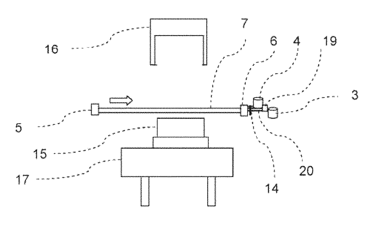
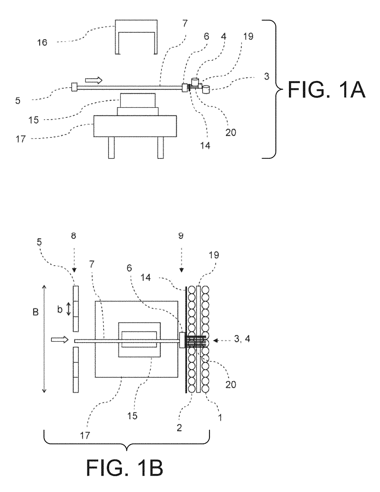
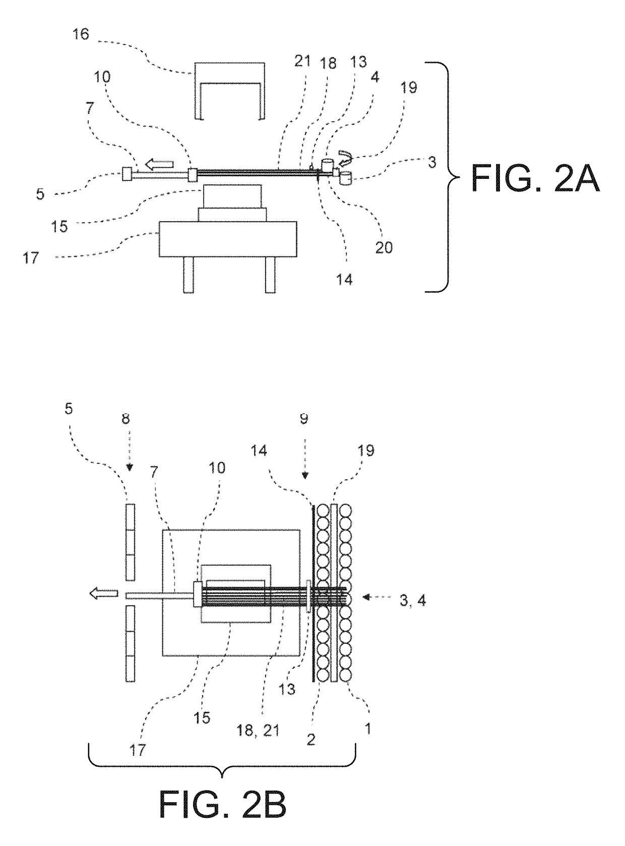
[0013]The present invention more specifically provides a device including a first molding tool having a draping position in the region of the connecting lines between the maximum positions and the thread transfer points, and a starting position outside the connecting lines. The first molding tool is rotatable and / or tiltable at least in the starting position and can also be moved into the respective draping position when rotated and / or tilted. Thus, due to simple, for example linear, paths for the grippers, a plurality of threads or rovings can be tensioned simultaneously and nevertheless several layers having different orientations can be draped successively on the molding tool. The unwind stations as well as thread guidance through the grippers can remain stationary. The desired orientation of the layer in regard to the eventual component can be achieved through rotation of the molding tool. Thus, a very flexible arrangement of the fiber preforms, and nevertheless a simple automation without complicated calculations of the thread travel paths is possible. The device is thereby configured such that it is capable of placing threads or roving material at rates of more than 2 kilograms per minute (kg / min) or even more than 3 kg / min.
[0014]Since the otherwise customary flat, semi-finished products are being foregone and instead the fiber preform is draped and produced directly from threads or rovings, material costs compared to known methods are much lower. A short production time can nevertheless be achieved through parallelization. The flat, semi-finished products are quite expensive because of prefabrication. With strongly three-dimensional components there is the additional risk of wrinkling when using large area, semi-finished products. In small area components on the other hand, the expenditure for cutting and joining of the individual components increases.
[0020]The first and / or a second molding tool can moreover be equipped with a heating device and / or a pressing unit. A binder already present in the layer can be activated through temperature or pressure increase, so that the threads or rovings are fixed in the predetermined shape and are initially joined into a layer and then into the fiber preform. Binder materials, for example threads or fleeces which consist at least partially of thermoplastic or adhesive can be draped at the same time. Thus, the binder material necessary for fixing is applied at the same time with the fibrous material. The binder material may also be introduced by hybrid threads containing binder material in addition to fibrous material, or by coating or spraying of the threads or rovings. The binder material may also be applied after draping of the threads and rovings over a molding tool, for example by spraying. Fixing of one layer of threads or rovings provides certain stability for the placement of an additional layer of threads or rovings, or for further processing of the fiber preform.
[0024]The grippers can assume different individual intermediate positions on their path, and can retain the respective origins of the threads or rovings at these intermediate positions. Various shapes can thereby be reproduced. And, only the amount of thread is tensioned by each gripper as is required for the respective location of the shape. The individual grippers can further be positioned on their path, following an outer contour of a molding tool. This means that the grippers hold on to the beginnings of the threads or rovings so that they are as close as possible to the point at which the fiber preform will have its edge at which the threads are separated after being formed on the molding tool. The grippers are therefore positioned where the respective threads or rovings leave the molding tool when it has been moved to the position for forming, or in the case of multi-part molding tools, when the molding tools have been moved together. This results in very little scrap of expensive fiber material, even with complex structures, which is especially important in batch production.
[0033]Tensioning occurs in such a way, for example, in that a plurality of separate grippers grip individual or a plurality threads or rovings at a plurality of thread transfer points allocated respectively to individual grippers. The grippers are then moved in substantially parallel paths relative to each other and the threads or rovings are thereby tensioned side by side. It is further feasible for several grippers to be moved simultaneously and independently of each other in one tensioning process. This allows the threads or rovings to be quickly tensioned parallel to each other and, in spite of this, each gripper can work independently.

Problems solved by technology

The flat, semi-finished products are quite expensive because of prefabrication.
With strongly three-dimensional components there is the additional risk of wrinkling when using large area, semi-finished products.
In small area components on the other hand, the expenditure for cutting and joining of the individual components increases.
Thus, also more complicated three-dimensional shapes can be produced in that a group of threads or rovings is draped or respectively reshaped between the two molding tools.

Method used


Image

  • Device and method for producing fiber preforms
  • Device and method for producing fiber preforms
  • Device and method for producing fiber preforms

Examples


Embodiment Construction

[0059]In accordance with an embodiment of the device and method according to the present invention, the inventive device is capable of carrying out the following process steps sequentially or partially parallel to one another:[0060]providing threads or rovings and possibly the binder material;[0061]gripping the required threads or rovings and possibly the binder material;[0062]tensioning the required threads or rovings by positioning the grippers accordingly;[0063]first draping over a first molding tool;[0064]second draping with a second molding tool;[0065]fixing the layer of threads or rovings;[0066]severing the threads or rovings on both sides of the molding tools;[0067]rewinding the released and unused threads or rovings;[0068]opening the molding tools;[0069]rotating and / or passing forward a molding tool with the applied layer.

Repetition of the sequence above for placement of additional layers in the same device or in one or a plurality of additional inventive devices, then yield...


PUM

PropertyMeasurementUnit
angleaaaaaaaaaa
angleaaaaaaaaaa
angleaaaaaaaaaa

Abstract

A device for producing fiber preforms including a plurality of unwind stations, a plurality of grippers and at least one first molding tool. Further, a method includes the successive steps of tensioning threads or rovings for a first layer with grippers, draping the first layer over a first molding tool, severing of the threads or rovings of the first layer, tensioning threads or rovings for a second layer with grippers, draping an additional layer over the first forming tool, and severing the threads or rovings of the second layer.

Description

CROSS REFERENCE TO RELATED APPLICATIONS[0001]This is a continuation of PCT application No. PCT / EP2012 / 051290, entitled “DEVICE AND METHOD FOR PRODUCING FIBER PREFORMS, WHICH ARE A PRECURSOR IN THE PRODUCTION OF FIBER REINFORCED PLASTIC COMPONENTS IN PARTICULAR”, filed Jan. 27, 2012, which is incorporated herein by reference.BACKGROUND OF THE INVENTION[0002]1. Field of the Invention[0003]The present invention relates to a device for producing fiber preforms, which in particular are a precursor in the production of fiber reinforced plastic components. The present invention moreover relates to a method—in particular when using the device—for producing fiber preforms, which are for example a precursor in the production of fiber reinforced plastic components.[0004]2. Description of the Related Art[0005]Fiber reinforced plastic consists of a matrix material which, among other factors provides the stiffness, and of fibers which are embedded into the matrix material and which, among other f...

Claims


Application Information

Patent Timeline
Patent Type & Authority Patents(United States)
IPC IPC(8): B29C70/20B29B11/16B29C70/56B29C70/38B29C70/54
CPCB29C70/56B29B11/16B29C70/382B29C70/541B29C70/207B29C2793/0027B29C2793/0081
Inventor GOTTINGER, MARCOKAISER, MICHAEL
Owner VOITH PATENT GMBH
Learn More