Heat Generating Body, Heat Insulating Method Using The Same And Packaging Material For Die Molding Heat Generation

a technology of heat generation body and heat insulating method, which is applied in the direction of exothermal chemical reaction heat generation, contraceptive devices, lighting and heating apparatus, etc., can solve the problems of large size, inability to achieve warming along the muscular or tendon direction, and inability to achieve exothermic performance of chemical substances

Active Publication Date: 2008-02-07
S T CORP
View PDF10 Cites 17 Cited by
  • Summary
  • Abstract
  • Description
  • Claims
  • Application Information

AI Technical Summary

Benefits of technology

The technical effect of this patent is that it provides a way to make a heat generator that helps alleviate common issues like stiff shoulders, lower back pain, muscle fatigue, menstrual cramps, and even poor blood flow. This method may also help reduce menstrual cramps specifically.

Problems solved by technology

The technical problem addressed in this patent text is the need for a heat generating composition that can be used for relaxing symptoms such as menstrual pain and poor circulation, while also being portable and easy to use. The text describes various heat generating compositions and their properties, and proposes various methods for improving them.

Method used


Image

  • Heat Generating Body, Heat Insulating Method Using The Same And Packaging Material For Die Molding Heat Generation
  • Heat Generating Body, Heat Insulating Method Using The Same And Packaging Material For Die Molding Heat Generation
  • Heat Generating Body, Heat Insulating Method Using The Same And Packaging Material For Die Molding Heat Generation

Examples


example 1

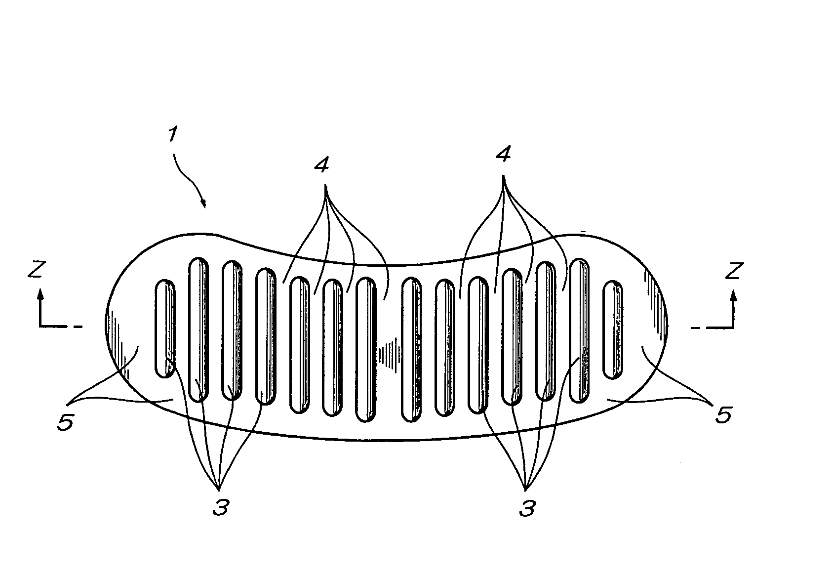
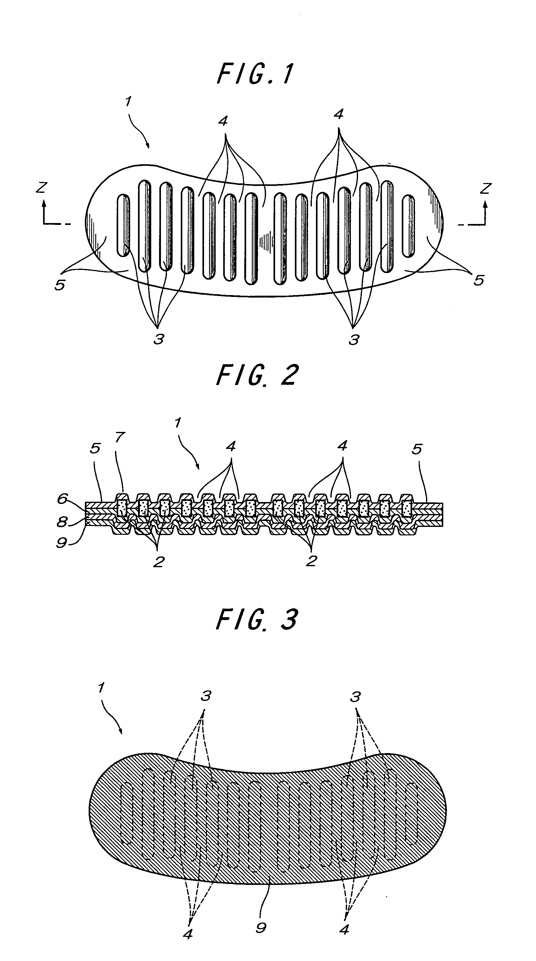
[0463] This Example will be described below with reference to FIG. 1 and FIG. 2.

[0464] A heat generating composition having a water mobility value of 8, which is a mixture consisting of 100 parts by weight of a reduced iron powder (particle size: not more than 300 μm), 7.0 parts by weight of active carbon (particle size: not more than 300 μm), 5.0 parts by weight of a wood meal (particle size: not more than 300 μm), 0.8 parts by weight of a water absorptive polymer (particle size: not more than 300 μm), 0.2 parts by weight of calcium hydroxide, 0.7 parts by weight of sodium sulfite and 11% of salt water, was used.

[0465] Next, the heat generating composition was molded by using a trimming die provided with seven cavities in a striped form in each of the right and left sides thereof. Incidentally, the cavities were provided at intervals of 10 mm only in the central part and at intervals of 5 mm in other part, respectively. Also, the dimensions of the cavities were 7 mm in width×80 m...

example 2

[0469] A reaction mixture having a water mobility value of less than 0.01, which consists of 100 parts by weight of a reduced iron powder (particle size: not more than 300 μm), 3.5 parts by weight of active carbon (particle size: not more than 300 μm), 4.0 parts by weight of a wool mean (particle size: not more than 300 μm), 2.2 parts by weight of a water absorptive polymer (particle size: not more than 300 μm), 0.2 parts by weight of calcium hydroxide, 0.7 parts by weight of sodium sulfite and 11% salt water, was charged as a heat generating composition in a contact treatment device vessel. Next, the upper portion of the contact treatment device vessel was opened to air, and the reaction mixture was subjected to self heat generation with stirring in the opened state to air under circumstances at 20° C. At a point of time when the temperature rise of the reaction mixture reached 40° C., the reaction mixture was sealed in an air-impermeable accommodating bag and cooled to room temper...

example 3

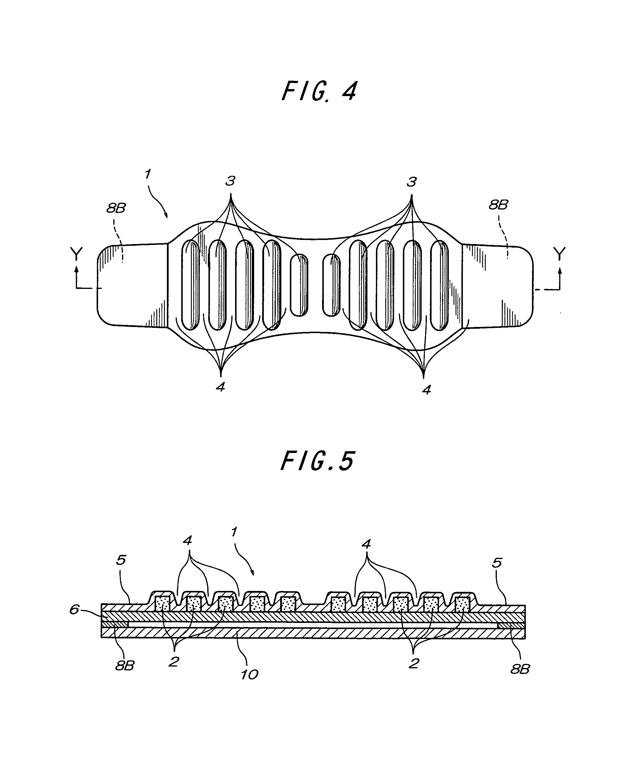
[0474] As shown in FIG. 4 and FIG. 5, a heat generating body 1 in a paper lantern-like shape having striped sectional exothermic parts 3 was produced in the same manner as in Example 2. However, in this Example, a pressure sensitive adhesive double coated tape was provided as an adhesive layer 8B on the surface opposite to the air-permeable surface in every end part in the longitudinal direction. The heat generating body 1 was fixed to a shoulder by the adhesive layers 8B and then subjected to an exothermic test for the body. As a result, the heat generating body had good adaptability to the shoulder. Furthermore, a temperature characteristic, curved surface fitness, winding properties and usefulness were evaluated. As a result, the heat generating body was superior in all of these evaluations.


PUM


Abstract

To provide a heat generating body which is able to relax symptoms such as stiff shoulder, low-back pain, muscular fatigue, menstrual pain, a symptom of poor circulation and in particular, can be suitably used for relaxation of a symptom of menstrual pain.
A heat generating body wherein a heat generating composition molded body resulting from molding a moldable heat generating composition containing surplus water as a connecting substance is interposed between packaging materials and the periphery of the heat generating composition molded body is heat sealed, which is characterized in that the packaging materials are each constituted of a substrate and a covering material; that the substrate is substantially planar and does not have an accommodating pocket; that the packaging materials each has a bending resistance of not more than 100 mm; that the packaging materials are each a non-elastic body at least at a temperature between 25° C. and 60° C., has a breaking strength of 500 g/mm2 or more at 25° C. and has a breaking elongation of 30% or more at 90° C.; that the moldable heat generating composition contains, as essential components, an iron powder, a carbon component, a reaction accelerator and water, has a water content of from 1 to 60% by weight, does not contain a flocculent aid, a flocculant, an agglomeration aid, a dry binder, a dry binding agent, a dry binding material, a sticky raw material, a thickener and an excipient, contains the surplus water so as to have a water mobility value of from 0.01 to 20, has moldability due to the surplus water, with the water in the moldable heat generating composition not functioning as a barrier layer, and is capable of causing an exothermic reaction upon contact with air; that plural sectional exothermic parts as divided by a sectioned part which is formed by heat sealing are provided; that the heat generating body contains a region having a ratio of bending resistance in the orthogonal directions of 2 or more on the surface thereof orthogonal to the thickness direction of the heat generating body; that at least a part of the heat generating body has permeability to air; and that the heat generating body has a fixing measure on at least a part of the exposed surface thereof.

Description


Claims


Application Information

Patent Timeline
Owner S T CORP
Why Eureka
Try Eureka