Imaging Apparatus

a technology of imaging apparatus and image, which is applied in the field of imaging apparatus, can solve the problems of difficult handling of the apparatus, difficult use restricted so as to increase the selectability of the imaging element, increase the resolution, and increase the flexibility of the design of the imaging apparatus

Inactive Publication Date: 2008-02-07
SONY CORP
View PDF1 Cites 2 Cited by
  • Summary
  • Abstract
  • Description
  • Claims
  • Application Information

AI Technical Summary

Benefits of technology

[0007] However, in the arrangement of the former using a mirror, there have been problems in that handling of the apparatus can be difficult because the whole apparatus becomes large in size due to necessities for a cubic volume of the mirror portion and for preventing occurrence of crack in and dirt on the mirror.
[0008] In contrast, the optical system of the latter realizing non-parallax has advantages in realizing reduction in size of the apparatus and handling of lens with ease similar to that of a normal lens without using a mirror.

Problems solved by technology

However, in the arrangement of the former using a mirror, there have been problems in that handling of the apparatus can be difficult because the whole apparatus becomes large in size due to necessities for a cubic volume of the mirror portion and for preventing occurrence of crack in and dirt on the mirror.
However, in the arrangement of the latter, since it is necessary to satisfy a condition under which the optical system including an imaging element is arranged within a space formed by lines passing from a non-parallax point (NP point) relative to a viewpoint center to outer circumferential portions of the lens in respective directions, use of the imaging element can be difficult unless the element is formed with a relatively small package.
Consequently, there has been a problem in that selectability of imaging elements can be restricted.

Method used


Image

  • Imaging Apparatus
  • Imaging Apparatus
  • Imaging Apparatus

Examples


Embodiment Construction

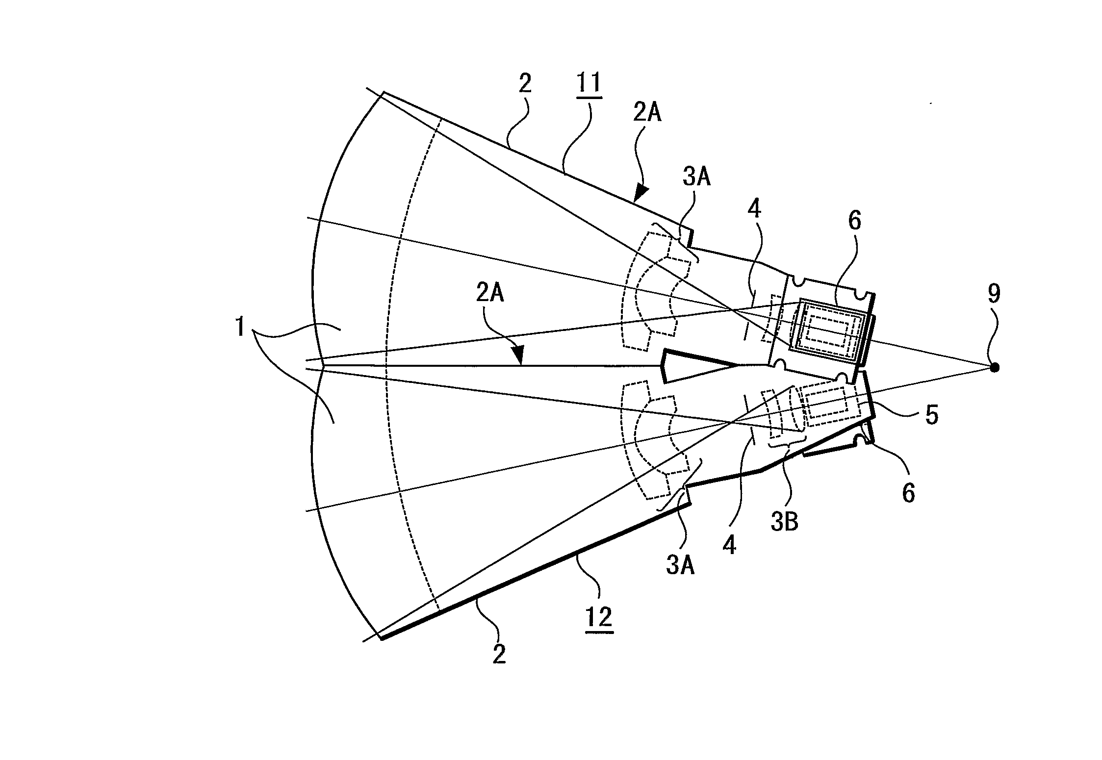
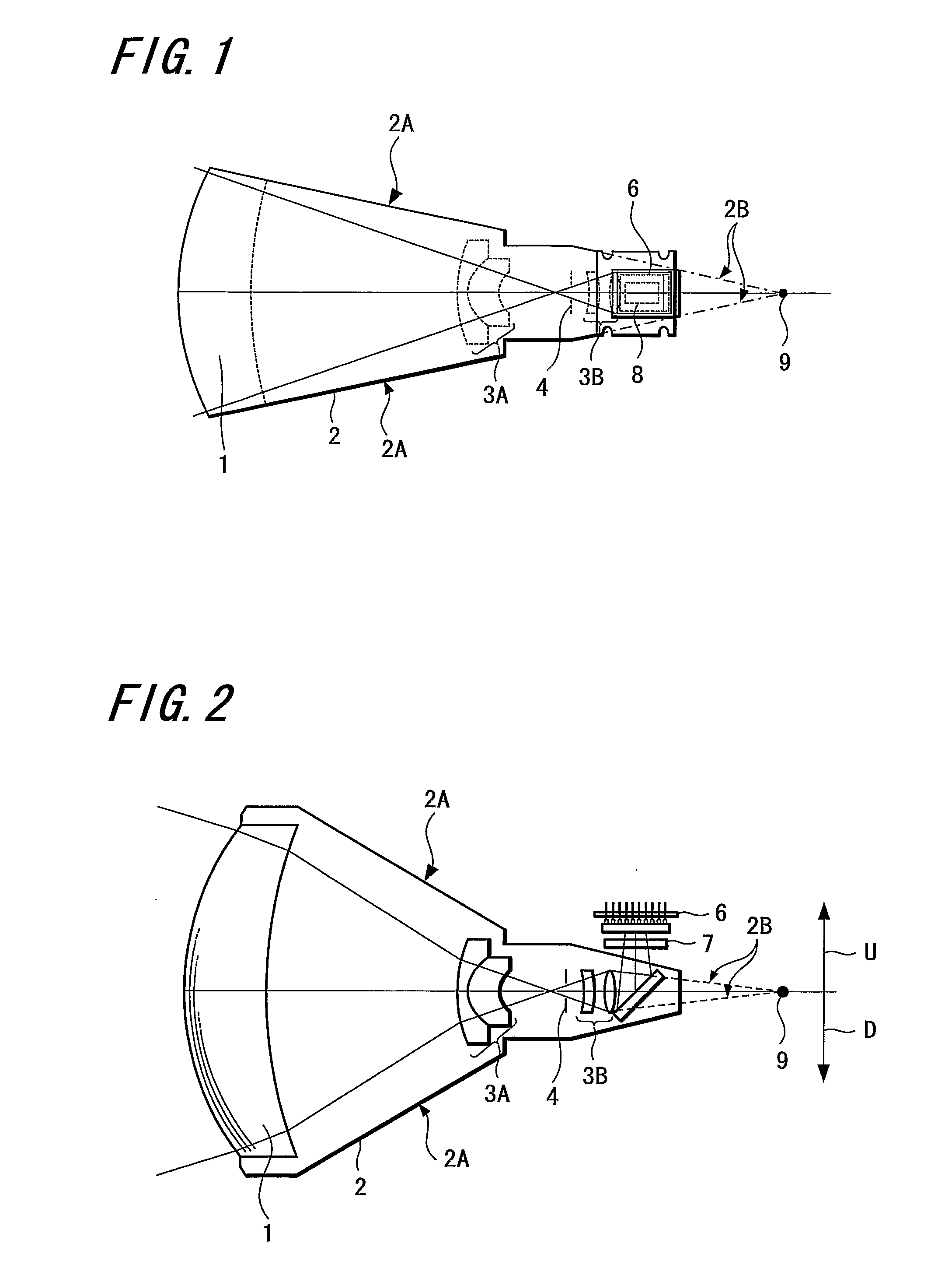
[0033]FIG. 1 and FIG. 2 show schematic views of one imaging unit (camera) forming an imaging apparatus as one embodiment of the present invention. FIG. 1 is a top view thereof and FIG. 2 is a side view thereof.

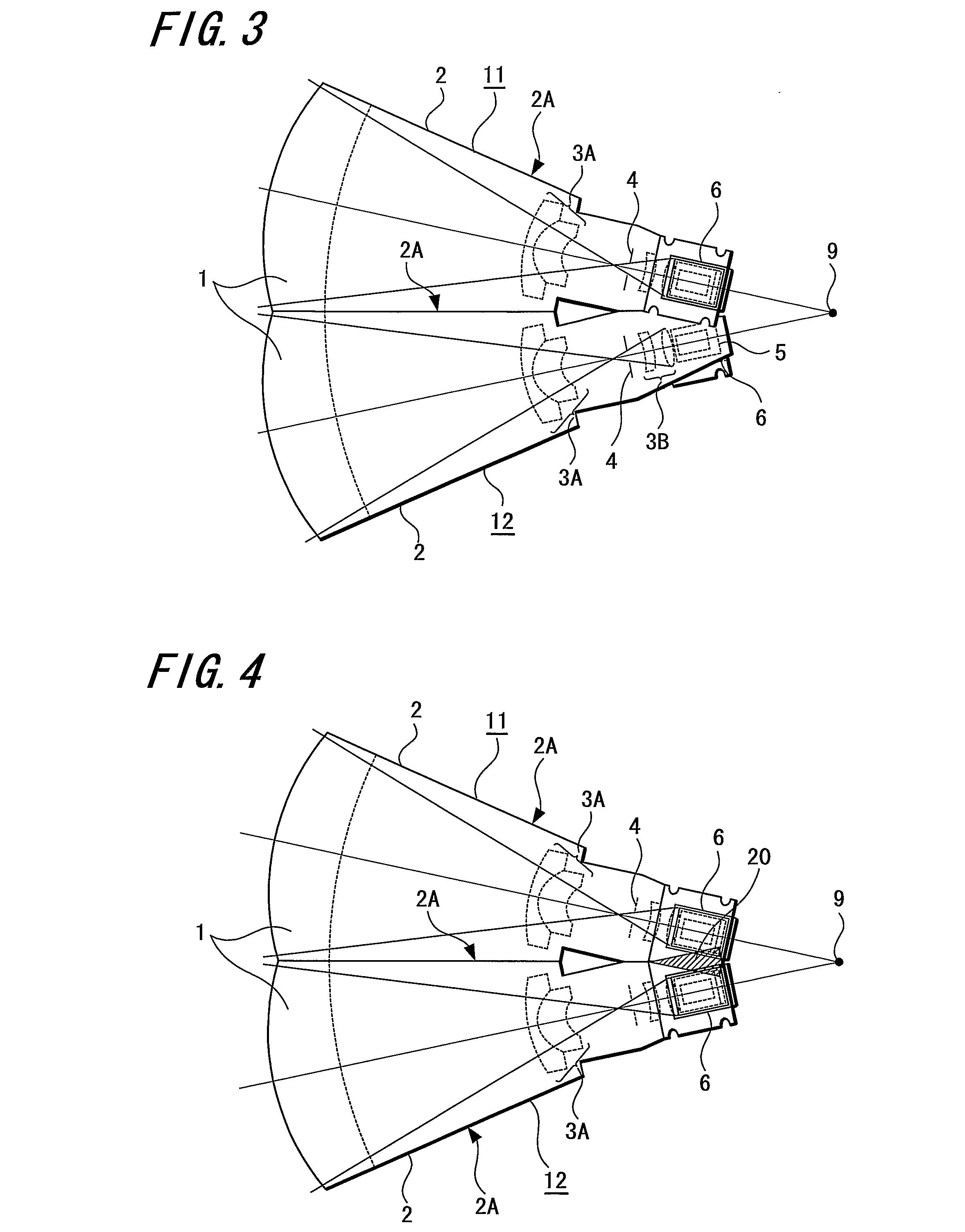
[0034] The imaging apparatus is formed by radially arranging a plurality of the imaging units (cameras) shown in FIG. 1 and FIG. 2 and attaching the imaging units adjacent to each other.

[0035] As shown in FIG. 1 and FIG. 2, each imaging unit (camera) includes a front lens piece 1 provided in the front end of the imaging unit, and lens groups (first lens group 3A and second lens group 3B) formed of a plurality of lenses located behind the backside of the front lens piece 1. In addition, an aperture diaphragm 4 is placed between the first lens group 3A and the second lens group 3B.

[0036] The front lens piece 1, the first lens group 3A, the second lens group 3B, and the aperture diaphragm 4 are respectively arranged inside a lens barrel 2 along the center axis of the lens barr...


PUM


Abstract

The present invention provides an imaging apparatus capable of imaging a wide area, controlling parallax to achieve an excellent image quality, and utilizing an imaging element with a relatively large package. The imaging apparatus for imaging a wide area as a subject by dividing the subject into a plurality of subject portions and respectively imaging the subject portions using a plurality of imaging means 11, 12 is configured such that the imaging means 11, 12 include lenses 1, 3A, 3B, and imaging element 6; respective NP points 9 of the a plurality of imaging means 11, 12 are concentrated within a minute radius region based on one of the NP points as a center; an optical element 5 having a reflection function is arranged behind a refraction surface of the lens 1 located at the nearest position from the subject in each of the imaging means 11, 12; the imaging element 6 is arranged behind the optical element 5 having the reflection function and outside of a space formed by straight lines which pass from the NP point 9 to circumferential portions in respective directions of the lens 1; and light beams bent by the optical element 5 having the reflection function are detected by the imaging element 6.

Description

TECHNICAL FIELD [0001] The present invention relates to an imaging apparatus capable of imaging a wide area, such as imaging all directions of the area, or the like. BACKGROUND ART [0002] As is well known in the related art, various types of cameras, each of which includes a number of video cameras housed in one chassis, have been developed for imaging all directions or an entire circumference simultaneously. [0003] In the arrangement of the above-mentioned camera, unless the viewpoint centers of the video cameras coincide with one another, a plurality of images cannot be stitched while maintaining high quality due to occurrence of parallax. [0004] Consequently, in order to solve the parallax problem, there have been proposed, for example, an arrangement where viewpoint centers of a plurality of cameras are virtually caused to approximately coincide with one another using a mirror (see Patent Document 1), an optical system capable of eliminating the parallax problem without using a ...

Claims


Application Information

Patent Timeline
Patent Type & Authority Applications(United States)
IPC IPC(8): G02B17/00
CPCG02B13/06G03B17/00H04N5/247H04N5/2254H04N5/23238G03B37/04H04N23/55H04N23/698H04N23/90
Inventor YOSHIKAWA, KOICHI
Owner SONY CORP
Why Eureka
Try Eureka