
Method for the reconstruction of a body map

a body map and reconstruction technology, applied in the field of body map reconstruction, can solve the problems of prior x-ray equipment drawbacks, large risk of collision between the detector and the patient, and the detector b>4/b> might collide with the patient,

Inactive Publication Date: 2008-02-07
GENERAL ELECTRIC CO
View PDF17 Cites 25 Cited by
  • Summary
  • Abstract
  • Description
  • Claims
  • Application Information

AI Technical Summary

Benefits of technology

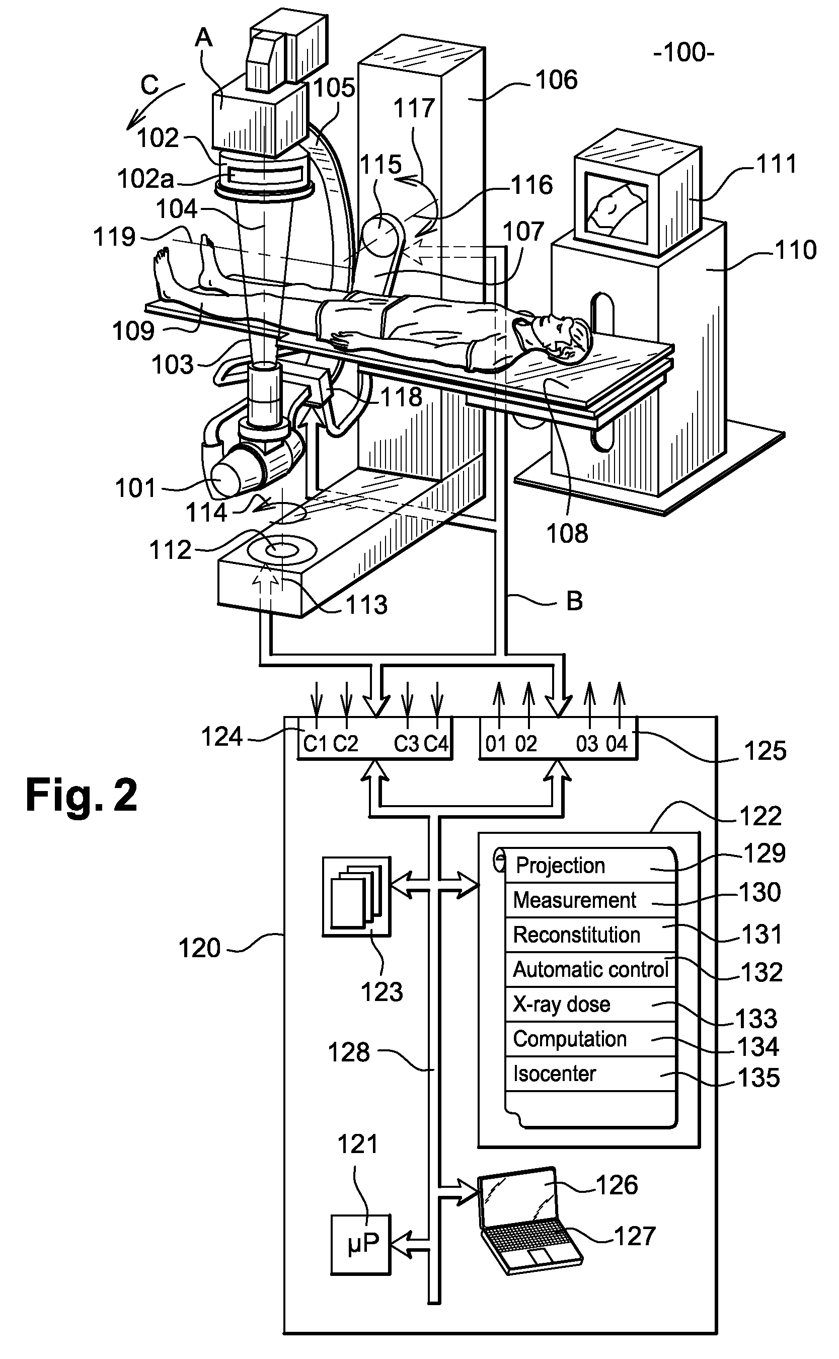
[0021]To do this, in addition to the conventional sensors, the detector has an antenna placed in the direction of emission of the x-rays. This antenna has electrodes. At each position of the moving parts around the patient, the electrodes simultaneously measure a distance between the patient's body and the detector. Prior knowledge of the position of the examination table relative to the detector in space makes it possible to assign a measured distance to each electrode of the antenna.
[0030]The volumetric reconstruction of the patient's body map enables the performance of verifications on the patient's position in order to detect any shift between two acquisition phases. This prevents the injection of contrast product if the patient has moved between two phases of an examination that requires a subtraction of images.

Problems solved by technology

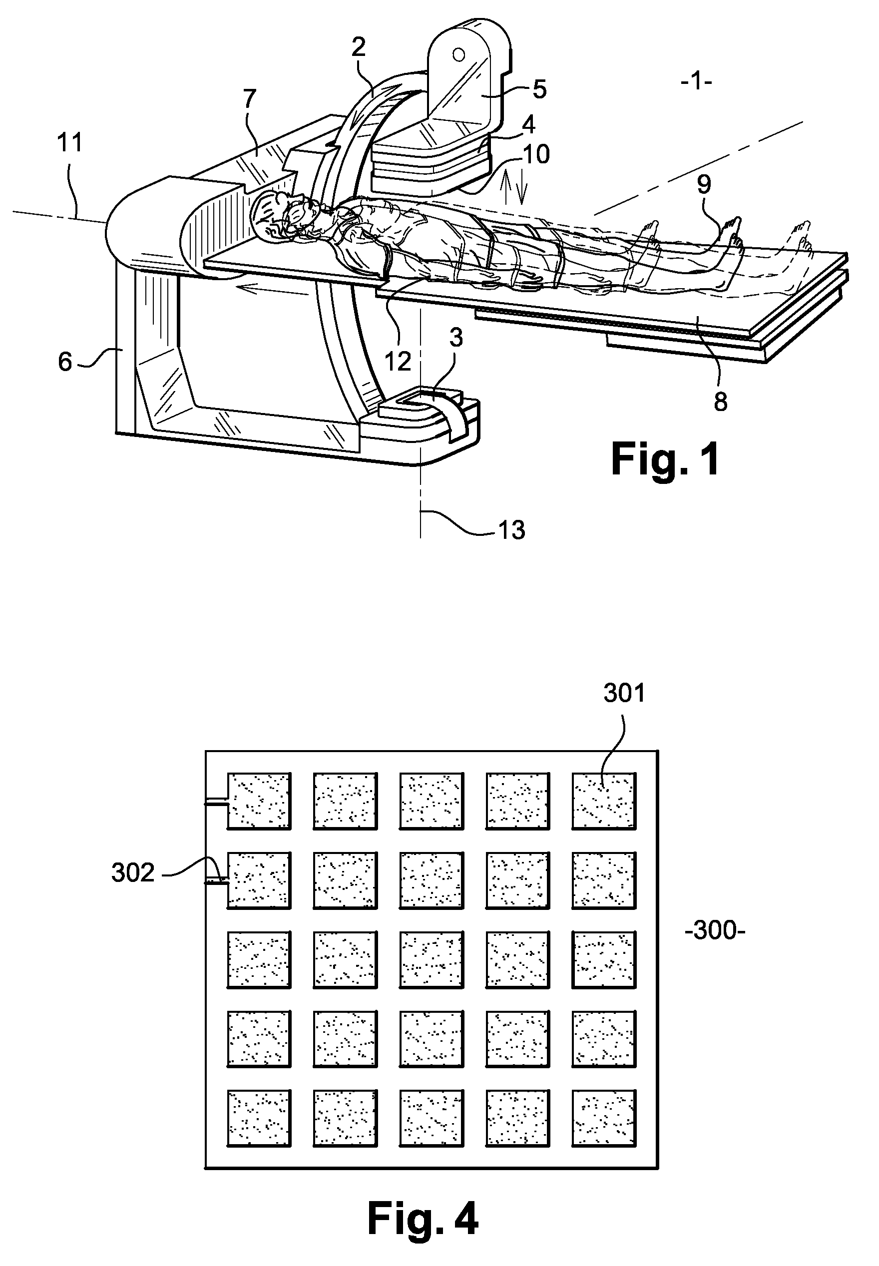
While this lift device is being lowered toward the patient 9, there is a risk that the detector 4 might collide with the patient 9.
However, these prior X-ray apparatuses have drawbacks.
During a radiology examination, when the patient's morphology is not the same as the morphology of the virtual patient, there is a very great risk of collision between the detector and the patient.
In this case, the detector is not close enough to the patient to give a high-quality image of the body part undergoing radiography, with a low dose of x-rays.
When the moving parts are at maximum speed, the practitioner is constantly afraid of injuring the patient.
As a result, the practitioner is under a certain degree of pressure when these moving parts are moving.
This leads to lower productivity in the X-ray machine.

Method used


Image

  • Method for the reconstruction of a body map
  • Method for the reconstruction of a body map
  • Method for the reconstruction of a body map

Examples


Embodiment Construction

[0083]FIG. 2 is a representation in space of a vascular type of X-ray apparatus 100 according to an embodiment of the invention. This apparatus 100 comprises for example an X-ray tube 101 as well as an X-ray detector 102. This tube 101 emits an X-ray beam 103 along a direction 104 of emission.

[0084]The tube 101 and the detector 102 are both hooked to the ends, on either side, of a C-arm 105. This arm 105, in the example of FIG. 2, is shaped like a hoop. The detector 102 is hooked to the arm 105 opposite the tube 101 and in the direction 104 of emission so as to receive the X-ray beam 103. The detector 102 is connected to a lift device A used to raise and lower said detector 102 in a direction of emission 104. The lift device A is connected to the arm 105.

[0085]The arm 105 is connected to an L-shaped post 106 by means of a rotating arm 107. A collimator situated at the end of the tube 101 can be used to convey a shape to the X-ray beam 103 emitted by the tube 101. Thus, this collimat...


PUM

PropertyMeasurementUnit
angleaaaaaaaaaa
angleaaaaaaaaaa
angleaaaaaaaaaa

Abstract

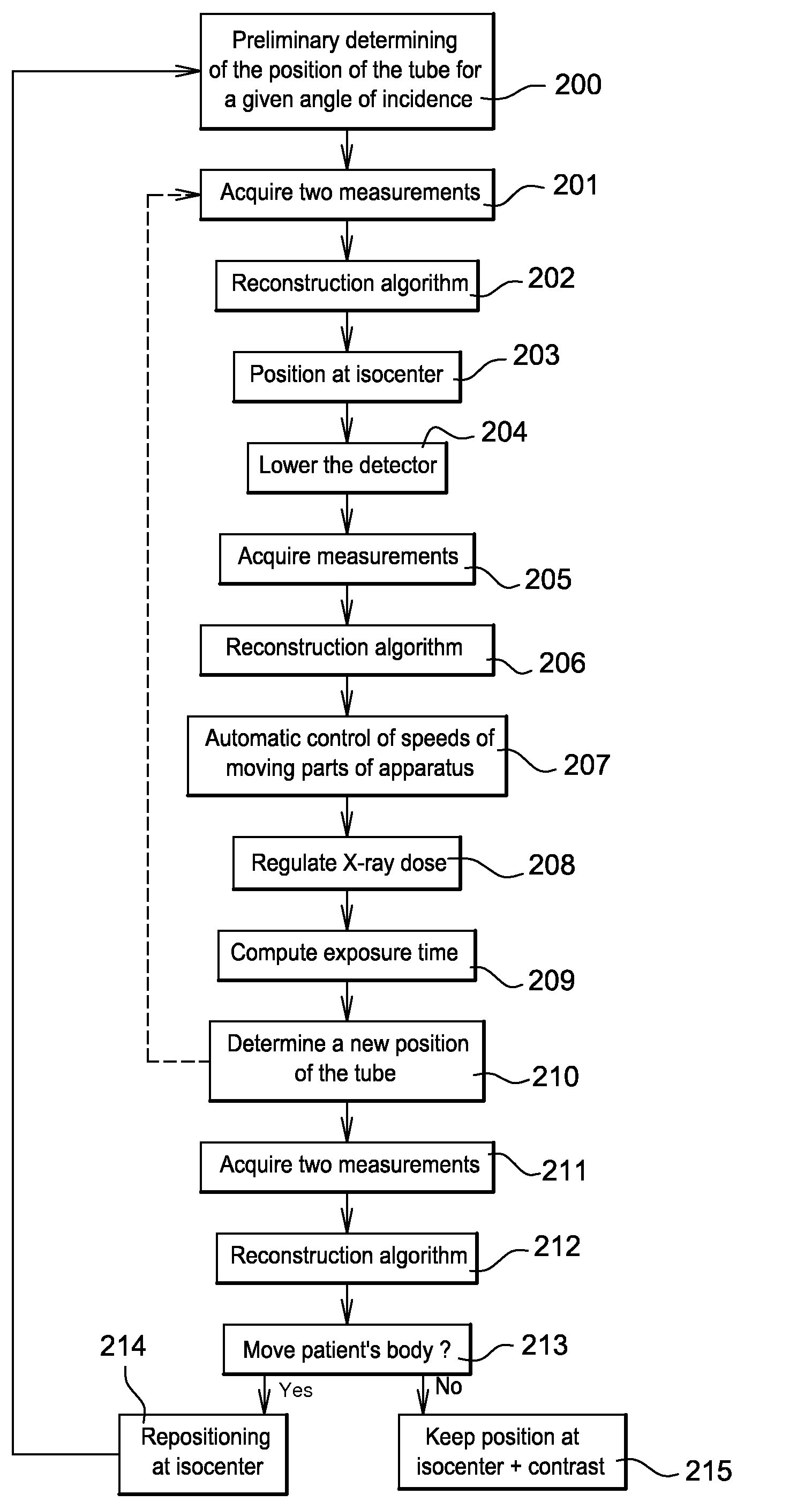
To perform a method for the reconstruction of a patient's body map, a detector has, in addition to the conventional sensors, an antenna placed in the direction of emission of the X-rays. At each position of the parts moving about the patient, electrodes of the antenna and the sensors simultaneously measure a distance between the patient's body and the detector. Means are used to carry out this reconstruction on the basis of the measured distances. The apparatus has means to achieve the following on the basis of this reconstruction: automatic control of the speeds of the moving parts of the apparatus, regulation of the X-ray dose and computation of the time of exposure to the X-rays.

Description

BACKGROUND[0001]1. Field of the Invention[0002]The field of the present invention relates to a method for the reconstruction of a body map. Embodiments of the present invention can be applied to special advantage but not exclusively in the fields of medical imaging, non-destructive X-ray controls and, more particularly, medical diagnostic apparatuses. The field of the invention also relates to an X-ray apparatus comprising a method of this kind for the reconstruction of a body map.[0003]2. Discussion of Related Art[0004]X-ray diagnostic apparatuses are X-ray image acquisition apparatuses. These apparatuses are used to obtain images, or even sequences of images, of an organ situated inside a living being, especially a human being. An example of an X-ray apparatus such as this is shown in FIG. 1.[0005]The X-ray apparatus of FIG. 1 has moving parts that enable it to rotate in different directions about a patient. These moving parts are capable of moving in all three dimensions of a spa...

Claims


Application Information

Patent Timeline
Patent Type & Authority Applications(United States)
IPC IPC(8): G06K9/00G01N23/04
CPCA61B6/102A61B6/4441A61B6/4423A61B6/545A61B6/589A61B6/488
Inventor BOUVIER, BERNARDFIVEL-DEMORET, ERIC
Owner GENERAL ELECTRIC CO
Learn More