

Hip Resurfacing Component
a technology for resurfacing components and hips, applied in hip joints, joint implants, medical science, etc., can solve problems such as significant pain for patients, weakening the femur, and reducing the problem of dislocation
- Summary
- Abstract
- Description
- Claims
- Application Information
AI Technical Summary
Problems solved by technology
Method used
Image

Examples
Embodiment Construction
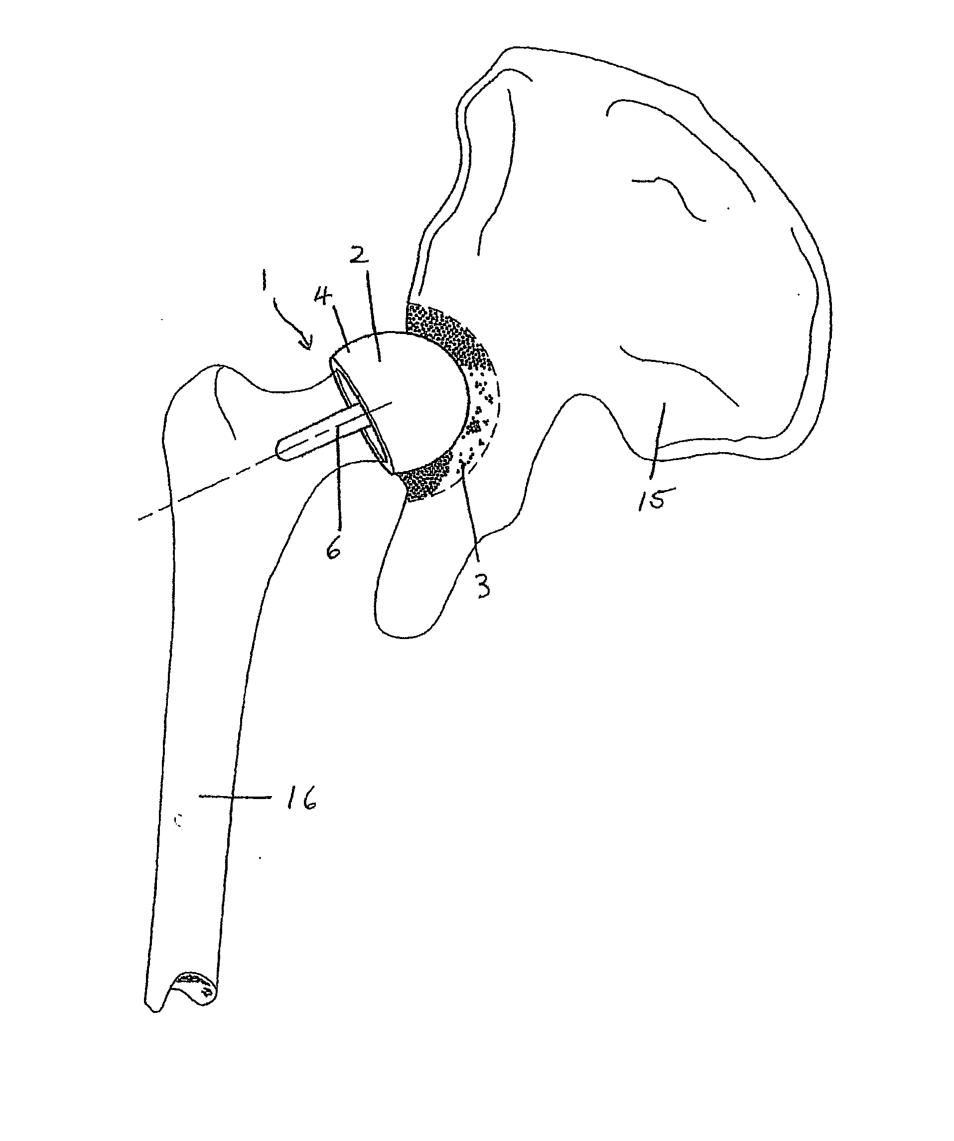
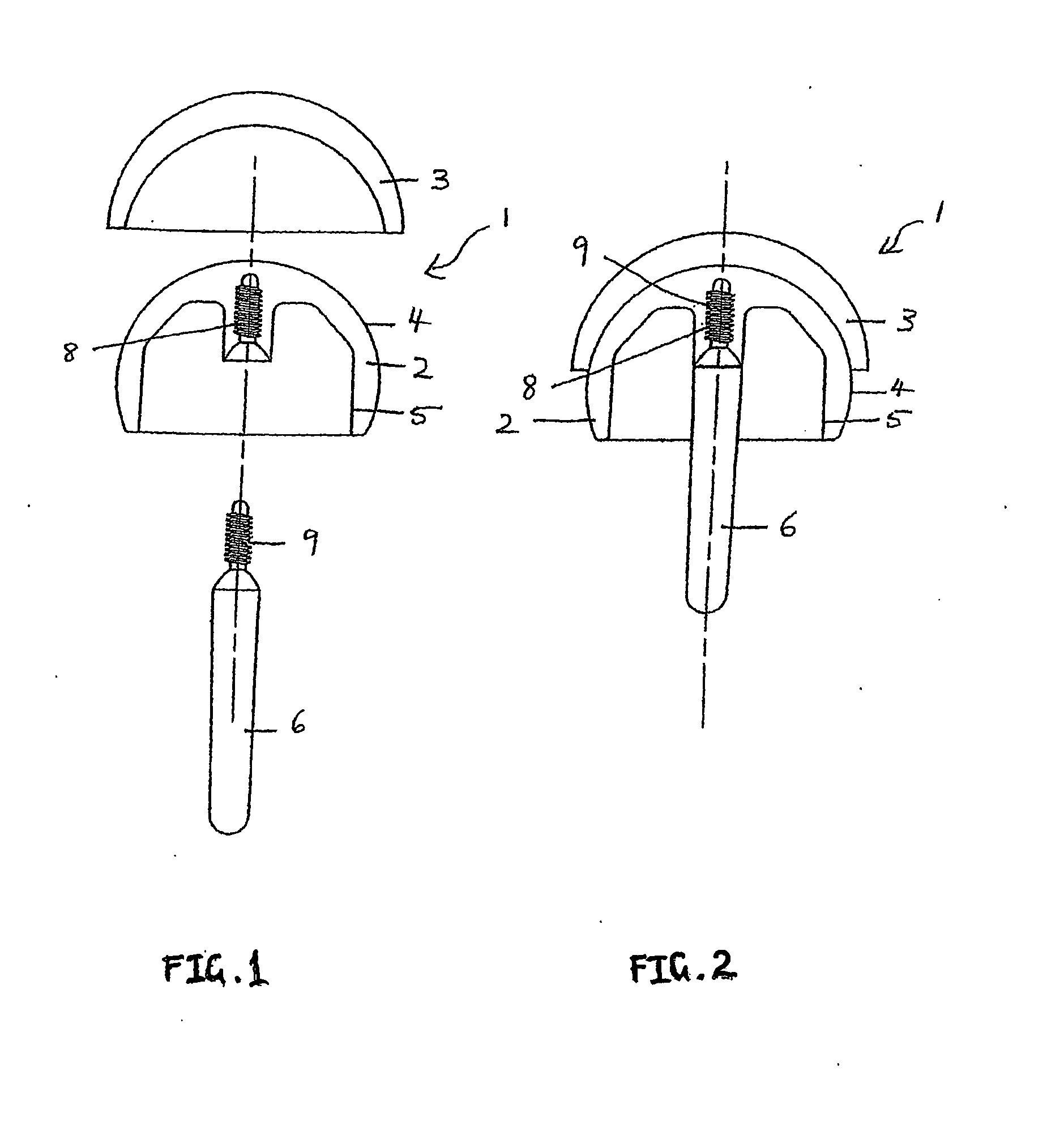
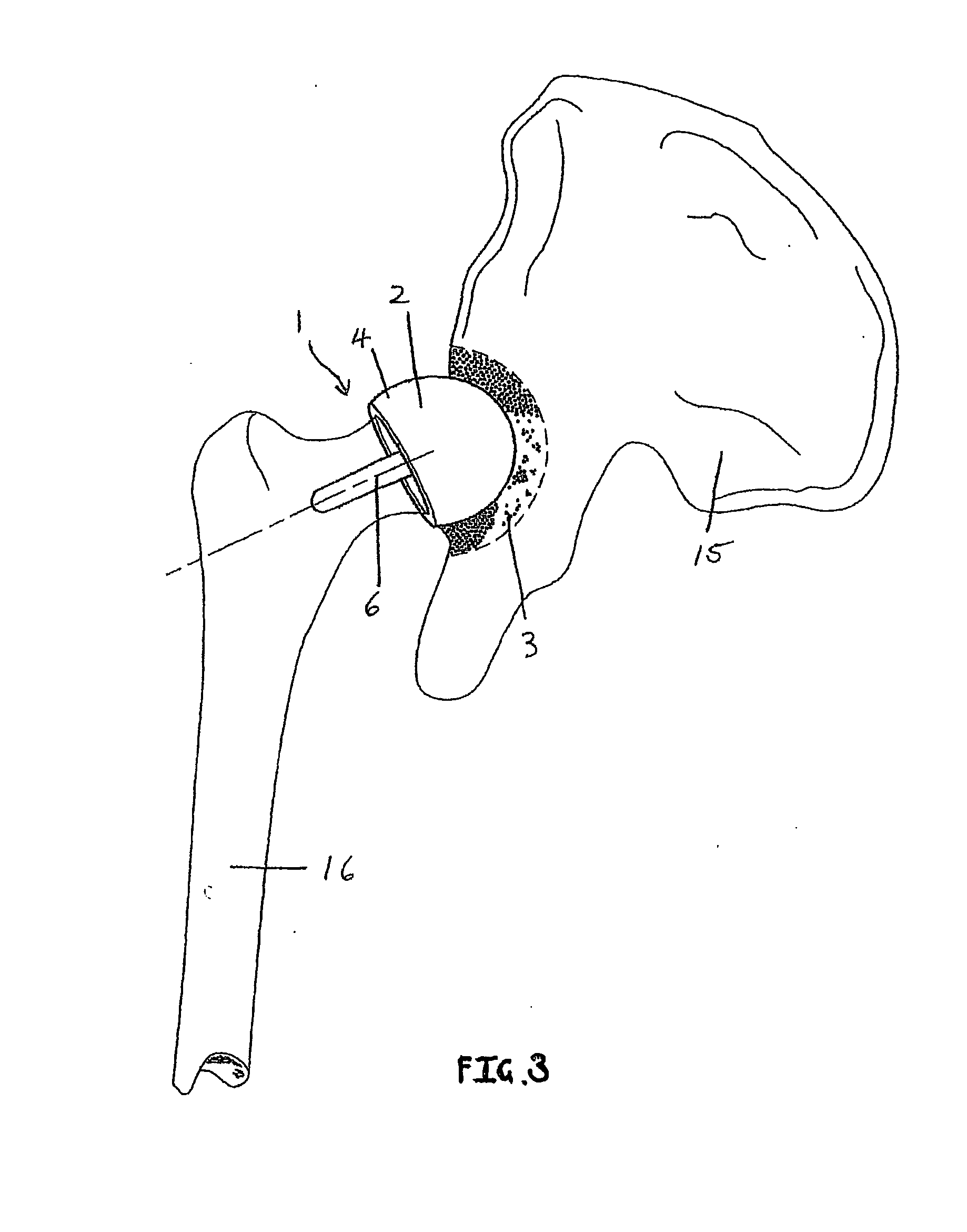
[0034] Referring to FIGS. 1-3 there is shown a femoral component 1 for a human hip resurfacing arthroplasty. The femoral component 1 comprises a femoral cap 2 with a convex surface 4 and a concave surface 5. The femoral cap 2 is adapted to engage with a cup 3. The femoral cap 2 and cup 3 are composed of a metal, such as steel.
[0035] The femoral cap 2 is adapted to be set onto a femoral bone 16 and also adapted to engage with the cup 3 that is set into the pelvic bone 15 of the patient. It can be seen that in use this engagement of the femoral cap 2 and cup 3 comprises a ball and socket joint.
[0036] The femoral component 1 further comprises a stem 6 that is adapted to be attached to femoral cap 2. The stem 6 is adapted to be removable from the femoral cap 2.
[0037] The femoral cap 2 includes threaded female cavity 8. The stem 6 has an upper end threaded end 9, which is adapted to engage with the female cavity 8. It can be seen that this allows the stem 6 to be readily removed from ...
PUM
| Property | Measurement | Unit |
|---|---|---|
| Solubility (mass) | aaaaa | aaaaa |
| Biodegradability | aaaaa | aaaaa |
Abstract
Description
Claims
Application Information