Variable geometry rim surface acetabular shell liner

a technology of acetabular shell and rim surface, which is applied in the field of acetabular prosthetic devices, can solve the problems of difficult and often imprecise fine tuning of the positioning of the acetabular component during the intraoperative assessment of range of motion and stability, and reducing the likelihood of dislocation or subluxation. , to achieve the effect of minimizing interference with the neck, maximizing the range of motion, and increasing the range of motion

Inactive Publication Date: 2007-05-10
SMITH & NEPHEW INC
View PDF20 Cites 51 Cited by
  • Summary
  • Abstract
  • Description
  • Claims
  • Application Information

AI Technical Summary

Benefits of technology

[0018] Methods and structures according to this invention include constrained liners and methods of producing constrained liners in which the rim surface geometry varies, rather than being set, in order to optimize the range of motion and minimize interference with the neck of the femoral component. This variable geometry rim surface is employed around the edge of the internal concave surface of the liner, where the opening meets the rim, and in some instances, a

Problems solved by technology

Because it is not currently possible to accurately measure the precise angle required for implantation of an acetabular component in a particular patient, it is difficult to place an implant at precisely the correct angle.
While a locking mechanism, such as a spline interface between the liner and the shell, is beneficial because it allows for multiple reorientations of the liner, fine tuning the positioning of the acetabular component during the intraoperative assessment of range of motion and stability is difficult and often imprecise.
Third, a broader range of motion decreases the likelihood of dislocation or subluxation, as it

Method used


Image

  • Variable geometry rim surface acetabular shell liner
  • Variable geometry rim surface acetabular shell liner
  • Variable geometry rim surface acetabular shell liner

Examples


Embodiment Construction

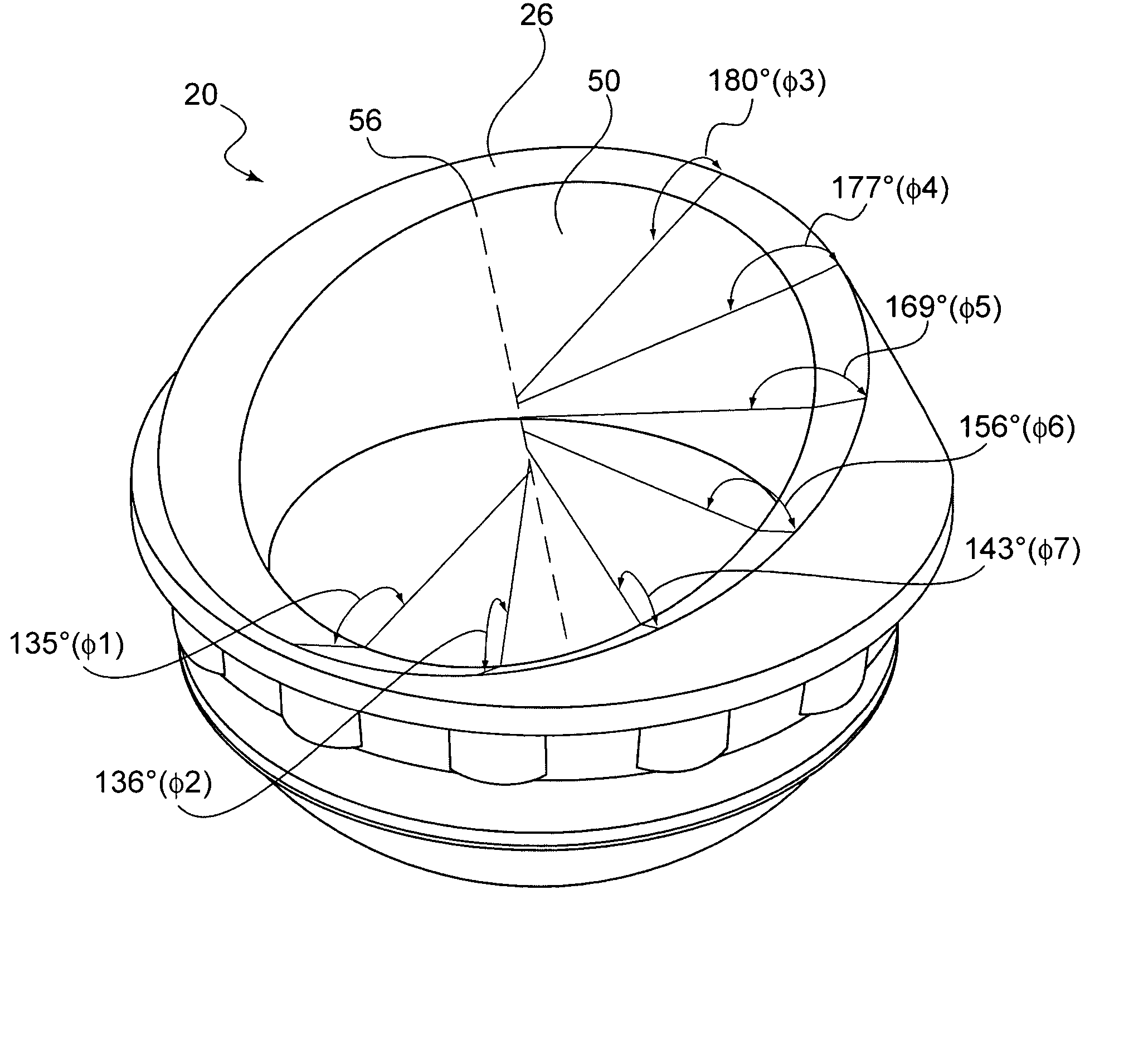
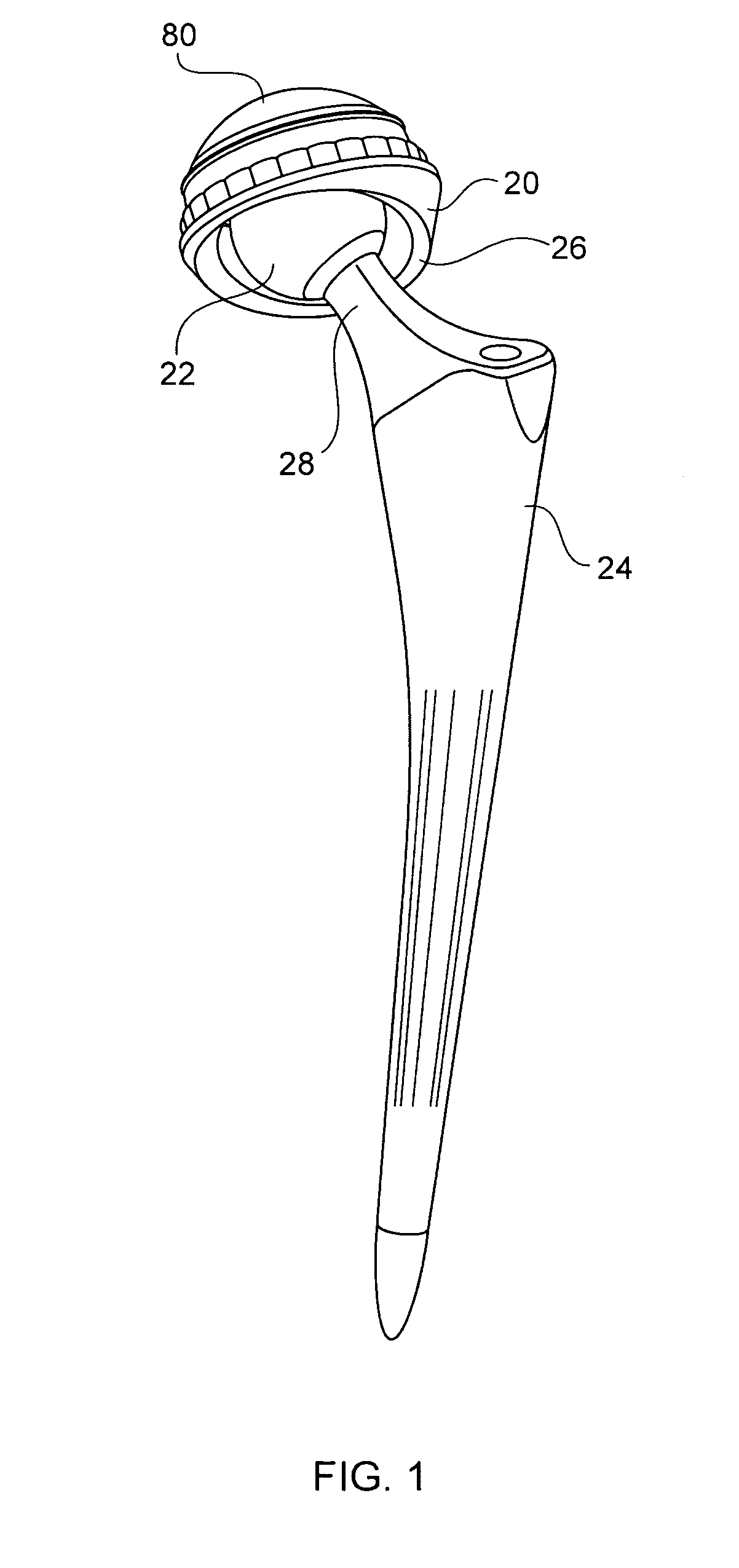
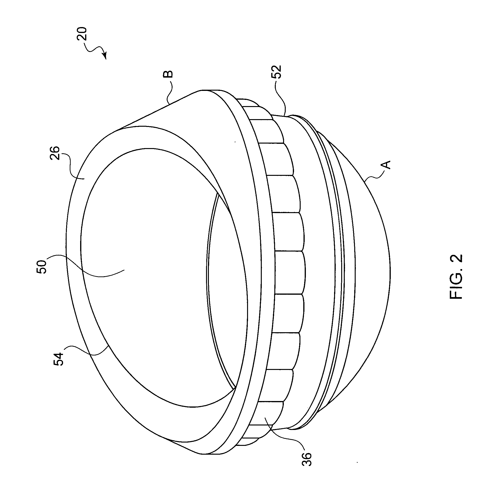
[0070] Methods and structures according to this invention seek to improve the range of motion of the femoral component of a hip prosthesis by varying the rim surface geometry of the rim of an acetabular shell liner in which the femoral component articulates, and particularly the rim geometry of a constrained liner. Varying the geometry of the rim surface relative to the internal concave surface opening or axis of the liner at different areas on the liner allows for optimization of the rim surface geometry, thus providing an increased range of motion. Liners with variable angle chamfer surfaces according to various embodiments of this invention have an overall range of motion generally at least comparable to a conventional constant geometry rim surface constrained liner.

[0071] Optimization of the acetabular shell liner rim surface geometry takes consideration of many elements in the design of the liner, including, but not limited to, range of motion of the femoral component, rotatio...


PUM


Abstract

There is provided an acetabular shell liner, and particularly a constrained liner, having a variable rim surface geometry to improve the range of motion of a femoral component within the liner and decrease the incidence of dislocation and subluxation. There are also provided methods of making and using the acetabular shell liner. Prosthetic devices, and particularly hip joint prostheses, containing the acetabular shell liner having a variable rim surface geometry are also provided.

Description

[0001] This application is a continuation-in-part and claims the benefit of U.S. non-provisional application Ser. No. 11 / 456,475, filed Jul. 10, 2006, titled “Variable Geometry Rim Surface Acetabular Shell Liner,” which is a continuation application that claims the benefit of U.S. non-provisional Application Ser. No. 09 / 808,228, filed Mar. 14, 2001 titled “Variable Geometry Rim Surface Acetabular Shell Liner,” now U.S. Pat. No. 7,074,241, which claims the benefit of U.S. Provisional Application Ser. No. 60 / 189,182, filed on Mar. 14, 2000, the entire contents of each of which are hereby incorporated by reference.BACKGROUND OF THE INVENTION [0002] This invention relates generally to acetabular prosthetic devices and more particularly to an improved acetabular shell liner wherein the liner has a variable geometry rim surface. [0003] Artificial implants, including hip joints, shoulder joints and knee joints, are widely used in orthopedic surgery. The human hip joint acts mechanically as...

Claims


Application Information

Patent Timeline
IPC IPC(8): A61F2/32A61F2/34
CPCA61B17/86A61F2/3094A61F2/30942A61F2/32A61F2/34A61F2/36A61F2/4637A61F2002/30112A61F2002/30153A61F2002/30158A61F2002/30324A61F2002/30332A61F2002/30367A61F2002/30403A61F2002/30487A61F2002/30495A61F2002/30499A61F2002/30616A61F2002/30787A61F2002/30952A61F2002/30975A61F2002/3233A61F2002/3401A61F2002/3411A61F2002/344A61F2002/3441A61F2002/3443A61F2002/3451A61F2002/3611A61F2002/3625A61F2002/365A61F2002/4631A61F2220/0025A61F2220/0033A61F2230/0004A61F2230/0019A61F2230/0026A61F2250/0036A61F2310/00011A61F2310/00179A61F2002/305A61F2002/3054
Inventor CROXTON, MICHAEL A.MCKINNON, BRIAN W.
Owner SMITH & NEPHEW INC
Why Eureka
Try Eureka