Method and apparatus for positioning a bone prosthesis using a localization system

a bone prosthesis and localization system technology, applied in the field of surgical navigation systems, can solve the problems of gyroscopic-based surgical navigation systems that are not as well established, gyroscopic sensors that do not provide information as to position per se, and weakness in the leg

Inactive Publication Date: 2009-09-29
AESCULAP AG
View PDF10 Cites 47 Cited by
  • Summary
  • Abstract
  • Description
  • Claims
  • Application Information

AI Technical Summary

Problems solved by technology

Gyroscopic-based surgical navigation systems are, perhaps, not as well established.
Note that gyroscopic sensors do not provide information as to position per se, but to acceleration or movement.
If the final configuration of the joint and bones results in an overall medialization (As compared to the original configuration), the muscles that attach to the pelvis will have reduced tension and a reduced lever arm, leading to weakness in the leg.
Specifically, while the reaming operation essentially dictates the final coordinate position of the cup and cannot be changed during cup implantation, the orientation of the cup actually can be affected during implantation of the cup.
Placement of a marker on the femur is time-consuming.
This is contradictory to the minimally invasive approach desired in modern orthopedic surgical procedures.

Method used


Image

  • Method and apparatus for positioning a bone prosthesis using a localization system
  • Method and apparatus for positioning a bone prosthesis using a localization system
  • Method and apparatus for positioning a bone prosthesis using a localization system

Examples


Embodiment Construction

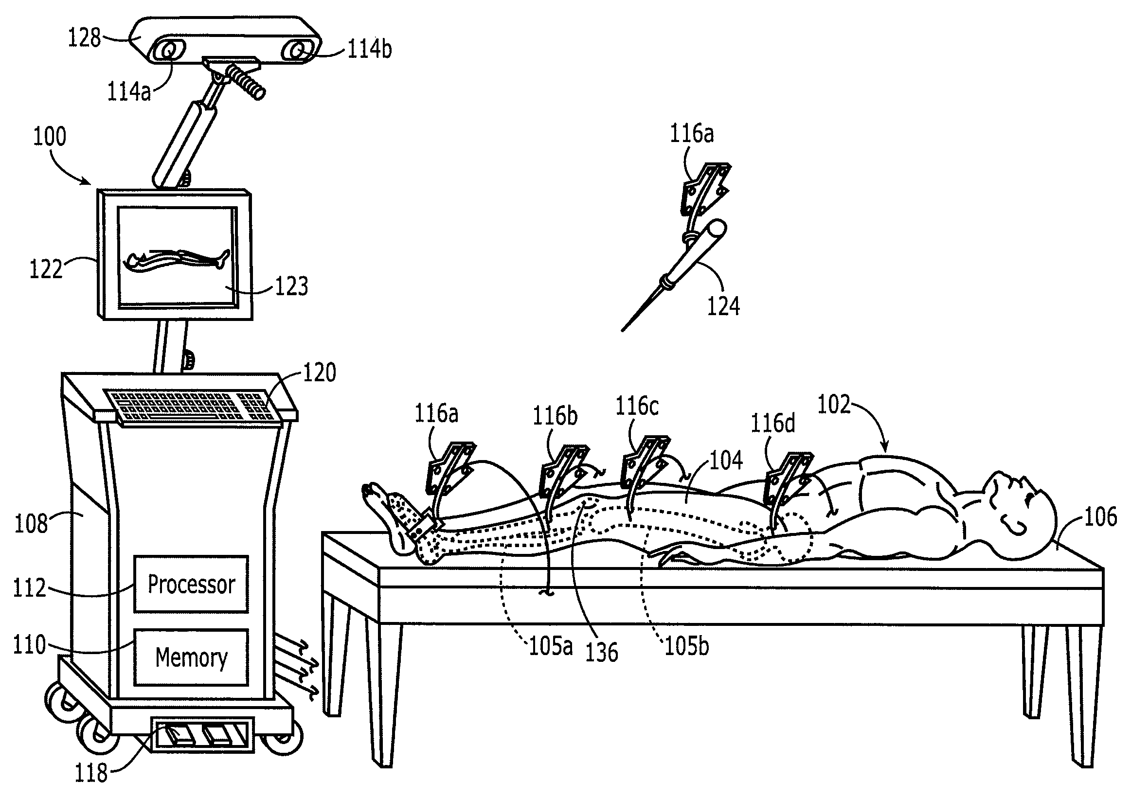
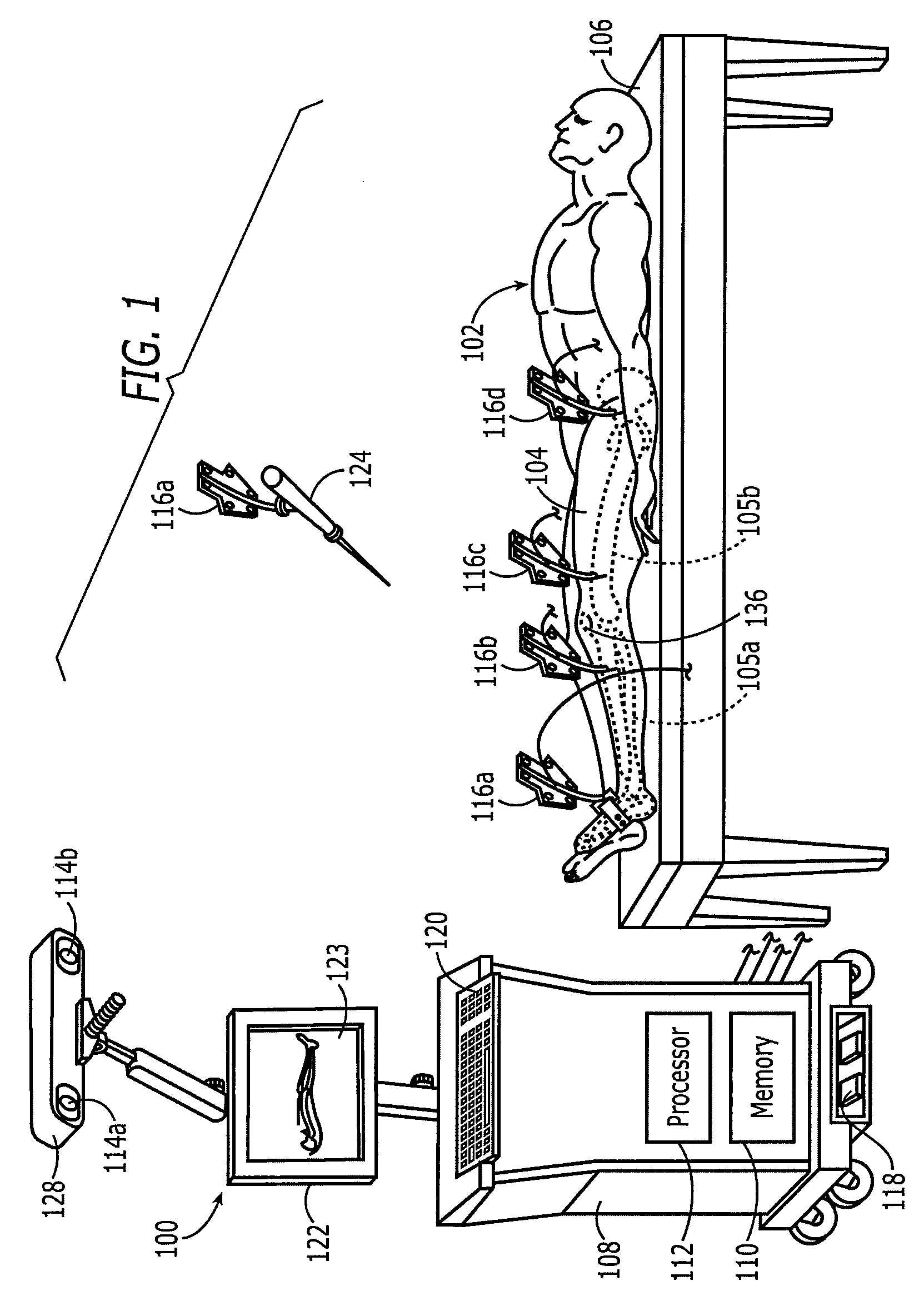
[0037]A description of a suitable optical localization device (surgical navigation system) for use in connection with the present invention is found in U.S. Pat. No. 6,385,475 to Cinquin et al., which is incorporated herein by reference. The invention will be described in connection with an infrared optical surgical navigation system such as disclosed in this patent. However, it should be understood that this is merely exemplary and that the present invention can be used in connection with many types of surgical navigation systems, including, but not limited to, surgical navigation systems that utilize optical, gyroscopic, electromagnetic, mechanical, and ultrasonic position / orientation sensing techniques.

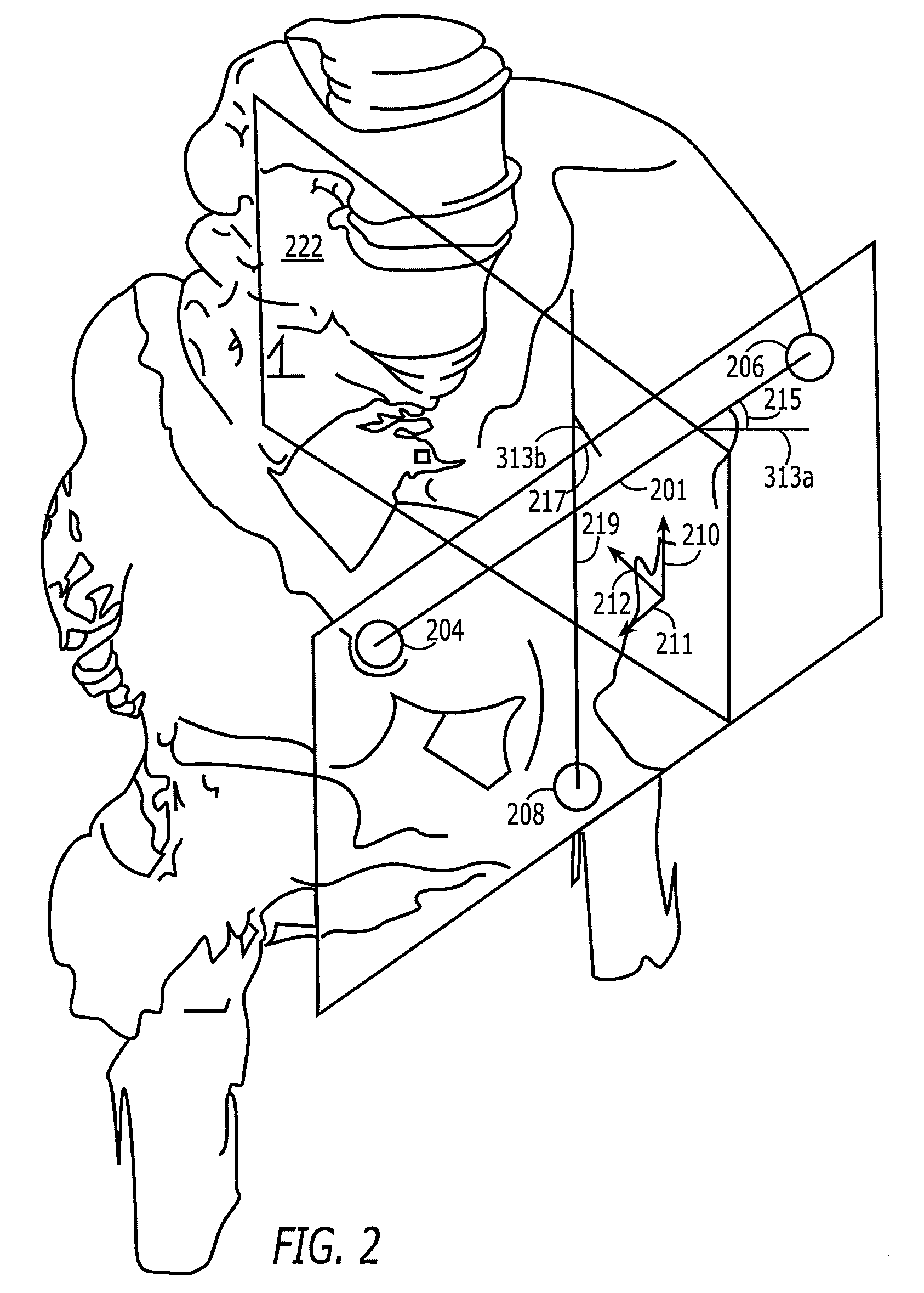
[0038]Below will be described the significant steps in an exemplary hip joint replacement surgical procedure utilizing concepts, methods, and apparatus in accordance with the present invention. It should be understood that the description is merely exemplary and that the invention ...


PUM


Abstract

Methods and apparatus using a surgical navigation system during hip joint replacement surgery without separately affixing a marker to the femur. The navigation system acquires the center of rotation of the hip joint as well as at least one point on the femur in the pelvic frame of reference. From these two points, the navigation system calculates the position and length of a first line between the center of rotation of the hip joint and the point on the femur. A prosthetic cup is implanted and its center of rotation is recorded. A tool for forming the bore within which the stem of the femoral implant component will be placed is tracked by the navigation system. The navigation system calculates the position and length of a first line between the center of rotation of the prosthetic cup and the re-palpated first point. The surgical navigation system uses this information to calculate and display to the surgeon relevant information about the surgery.

Description

BACKGROUND OF THE INVENTION[0001]The present invention relates to surgical navigation systems, sometimes called localization devices. More particularly, the present invention relates to methods and apparatus for positioning a bone prosthesis during orthopedic surgery using a surgical navigation system.[0002]Many different types of surgical navigation systems are known, including surgical navigation systems that rely on optical, electromagnetic, mechanical, ultrasonic, and gyroscopic position and / or orientation sensing techniques and apparatus. Optical-, electromagnetic-, mechanical-, and ultrasonic-based surgical navigation systems are well known at this time. Gyroscopic-based surgical navigation systems are, perhaps, not as well established. Gyroscopic systems use inertial sensors. In gyroscopic systems, each marker comprises one or more gyroscopes. If six gyroscopic sensors are incorporated on a rigid body marker, namely, three sensors for detecting force and / or acceleration in li...

Claims


Application Information

Patent Timeline
Patent Type & Authority Patents(United States)
IPC IPC(8): A61F2/32
CPCA61F2/34A61F2/4609A61F2002/3401A61B90/36A61B2034/2055A61B2034/2068A61B34/20A61B34/25A61B34/10A61B2034/107A61B2034/108
Inventor KAMMERZELL, SERGEJBADER, UWEMOLLARD, BENOIT
Owner AESCULAP AG
Why Eureka
Try Eureka