Method and apparatus for hip femoral resurfacing tooling

a technology for femoral resurfacing and tooling, which is applied in the field of system, kit and method for joint prosthesis installation tools, can solve the problems of adversely affecting the goal of satisfactorily restoring, affecting the fixation of components, and affecting the performance of these implants

Inactive Publication Date: 2008-05-08
HOWMEDICA OSTEONICS CORP
View PDF74 Cites 47 Cited by
  • Summary
  • Abstract
  • Description
  • Claims
  • Application Information

AI Technical Summary

Benefits of technology

[0021]It is an object of the present invention to provide a more successful surface replacement of the femoral portion of a total hip replacement bas

Problems solved by technology

The satisfactory performance of these implants can be affected not only by the design of the component itself, but also by the surgical positioning of the implanted component and the long-term fixation of the implant.
Improper placement or positioning of the implant can adversely affect the goal of satisfactorily restoring the clinical bio-mechanics of the joint as well as impairing adequate fixation of the component when implanted.
This is especially important since installation of an orthopedic implant often involves an extensive and difficult medical procedure, and therefore replacement or revision of the installed implant is typically difficult and traumatic.
These stem type prostheses are very successful but when they fail the stem can create considerable damage inside the bone.
The implant can move about inside the bone causing the intramedullary cavity to be damaged.
Because a stiff stem transmits the forces more directly into the femoral shaft, such implants have the further disadvantage that they can weaken the surrounding bone nearer to the hip joint due to stress shielding.
While this method of fixation by cement provides immediate fixation and resistance to the forces encountered, and allows the surgeon to effectively position the devi

Method used


Image

  • Method and apparatus for hip femoral resurfacing tooling
  • Method and apparatus for hip femoral resurfacing tooling
  • Method and apparatus for hip femoral resurfacing tooling

Examples


first embodiment

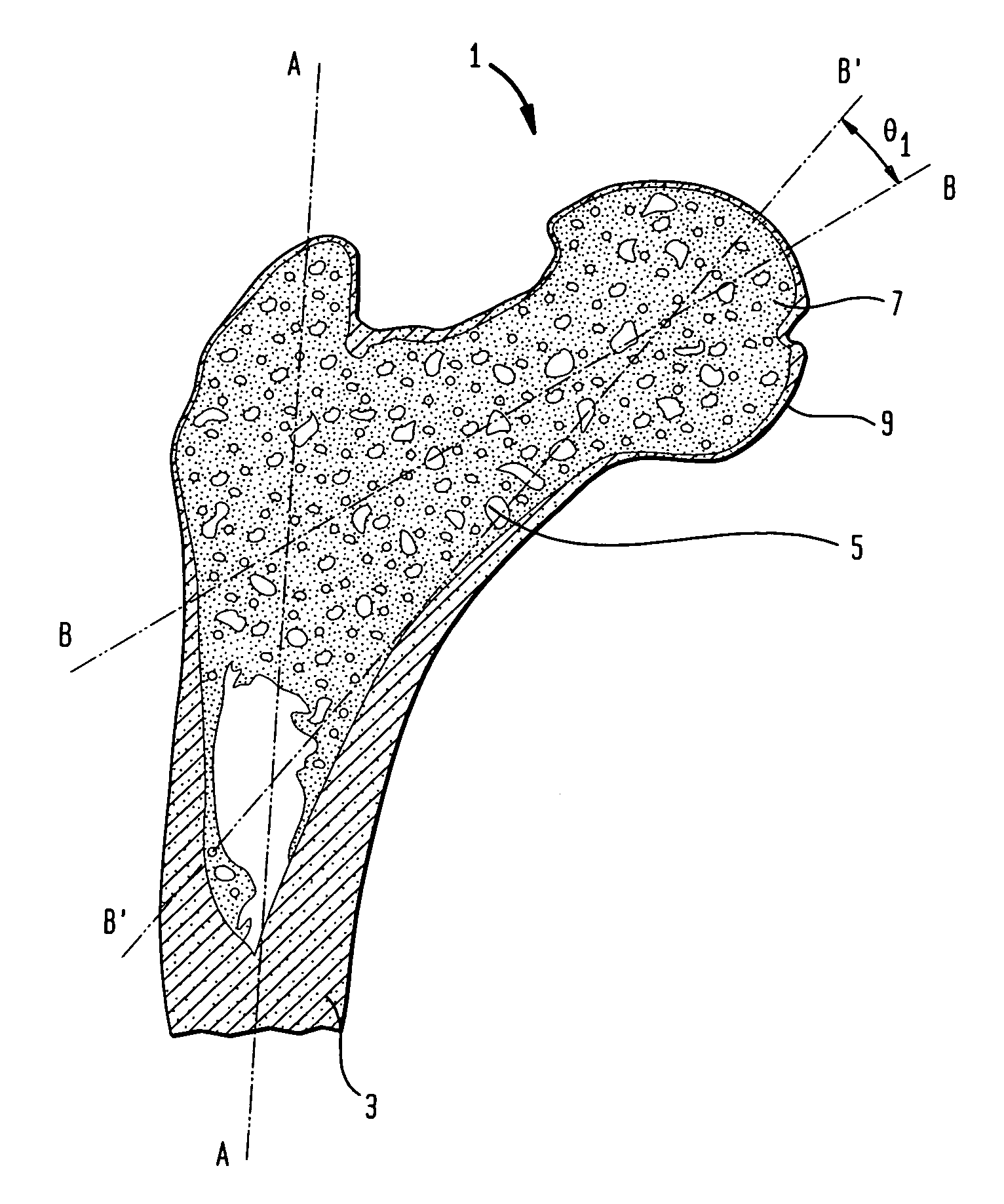
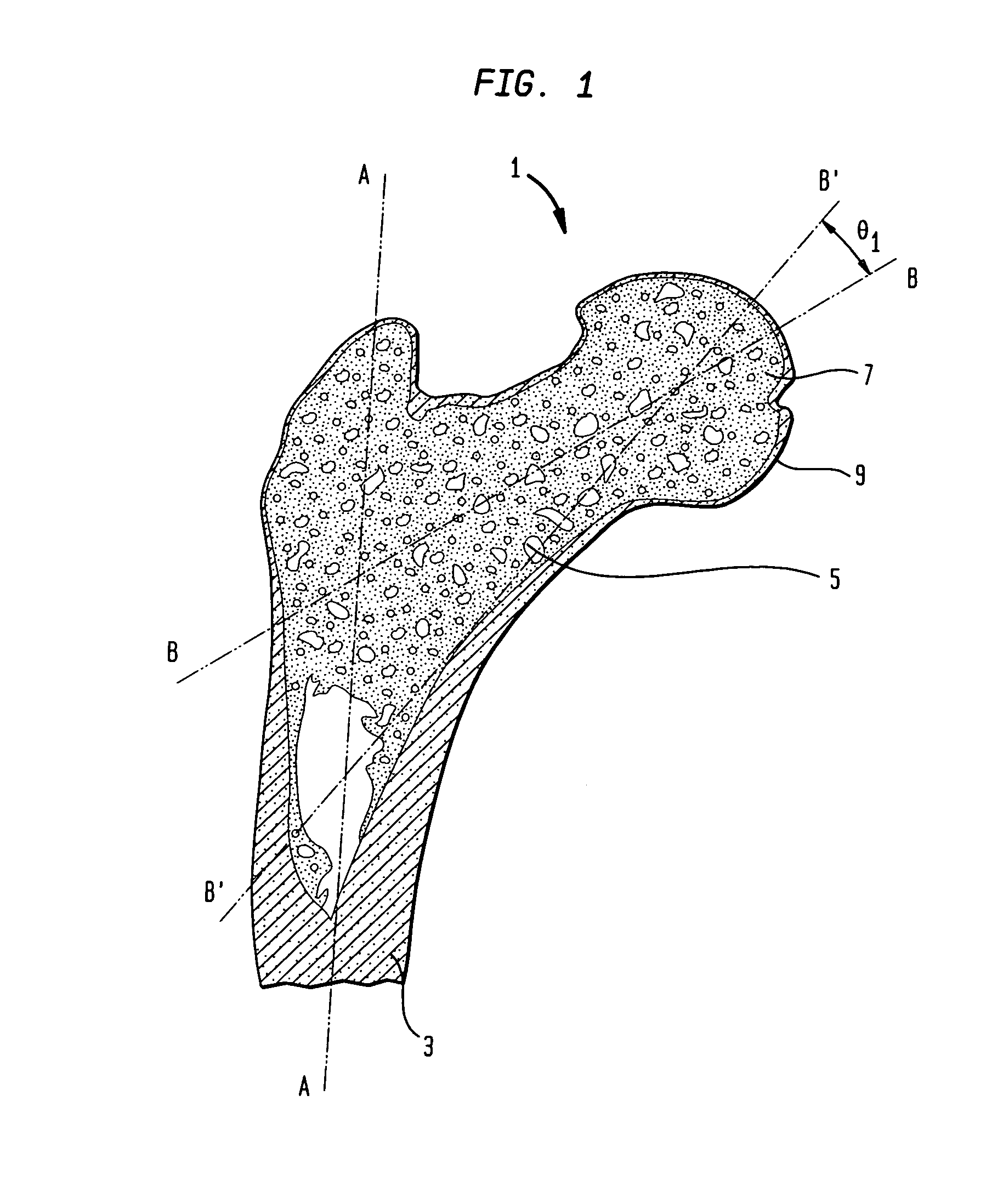
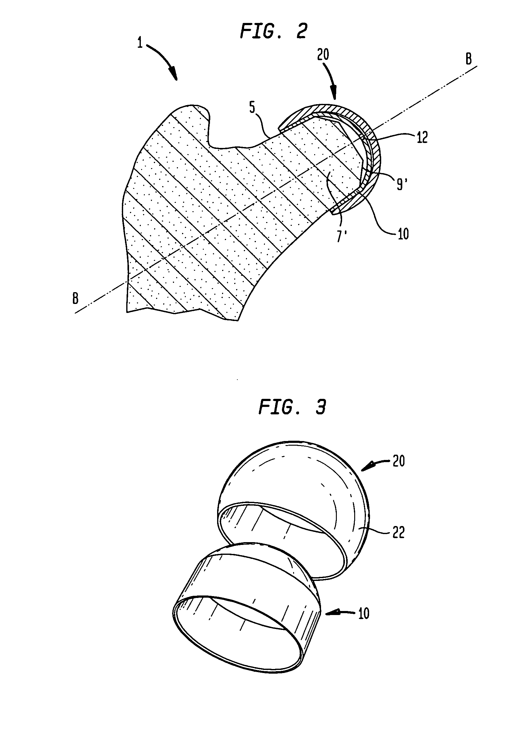
[0047]FIGS. 5 and 6 depict a prosthesis holding tool 50 according to an aspect of the invention for seating the sleeve component 10 of a two-part prosthesis onto the prepared femoral head 7′ of the femur 1. The tool 50 is cannulated with a central bore 51 to allow guiding on the guide pin 30 initially used to prepare the femoral head. The sleeve 10 has a central hole 12 in the proximal portion to allow the guide pin 30 to pass through it. The central bore 51 of the tool 50 is capable of receiving the guide pin 30 and slidingly journaling on the guide pin to insure that the tool is aligned with the prepared femoral head axis B-B while seating the sleeve. The tool distal portion has a sleeve interface 52 for receiving the sleeve 10. The sleeve interface 52 has holding features 54 that conform to a portion of the sleeve outer surface and retain the sleeve with suitable features such as detents 55 or tines. Because of the preferred tapered sleeve exterior configuration wedging with the ...

third embodiment

[0052]FIGS. 13-19 show tools and methods according to an aspect of the invention wherein an alignment jig 80 is attached to a femoral neck 5 to install a ball prosthesis 20′ on a prepared femoral head 7′ along a prepared femoral head axis B-B determined from the guide pin 30. In this embodiment, the invention is used to seat the ball component 20′ rather than the sleeve 10. The ball component 20′ depicted is a one-piece type prosthesis with a cavity fitting directly on the prepared femoral head 7′ although the aspects of the invention applicable to a one-piece ball component 20′ are also applicable to any modular ball component such as ball component 20. Fitting a ball component 20′ presents problems because the axis B-B cannot be directly located by the datums of the previous embodiments, either by guiding on the guide pin 30 or the bore 31, during the installation of the ball because the pin must be removed prior to installing the component and the bore is inaccesible as the head ...

second embodiment

[0053]Turning to FIG. 13, the alignment jig 80 is attached to a proximal portion of the femur 1, preferably at the femoral neck 5. The femoral head 7 has been prepared, as previously discussed with respect to FIG. 4 and the guide pin 30 is temporarily left in place. The alignment jig 80 is comprised of a femoral mount 81, an axial extension 82 and a radial extension 84 with a pin location guide 86 at the proximal end of the extension. The pin location guide 86 is an aperture having a central axis that can be aligned to be co-axial with the femoral head axis datum provided by the guide pin 30 or the bore 31 and consequently with axis B-B. The jig 80 has various clamps, slides and rotational adjustments that provide sufficient degrees of freedom to allow the pin location guide 86 to be co-axially positioned with axis B-B. The pin locator 87 has a bore with a central axis. The bore is sized to slidingly engage on the guide pin 30 projecting from the femoral head and the locator 87 has ...


PUM

PropertyMeasurementUnit
Angleaaaaaaaaaa
Distanceaaaaaaaaaa
Forceaaaaaaaaaa

Abstract

Tools and methods for implanting hip resurfacing femoral prostheses along a path defined by the axis of a shaped femoral head surface are described. The prostheses are stemless partial ball components having an outer surface shaped to conform to an acetabular socket and may be a two part design having a mating sleeve component with an internal bore adapted to receive the shaped femoral head. The tools and methods are capable of accurately implanting both one and two piece ball components and sleeves without requiring the prosthesis to have a central stem or the preparation of a stem cavity in the femoral head and neck.

Description

BACKGROUND OF THE INVENTION[0001]The present invention relates generally to systems, kits and methods for joint prosthesis installation tools. The present invention includes jigs and methods for installing a stemless ball component to a prepared femoral head along an axis defined by the prepared femoral head and jigs for installing a sleeve component for adapting a ball component to a prepared femoral head along an axis defined by the prepared femoral head.[0002]Artificial joint prostheses are widely used today, restoring joint mobility to patients affected by a variety of conditions, including degeneration of the joint and bone structure. Typically, the failed bone structure is replaced with an orthopedic implant that mimics, as closely as possible, the structure of the natural bone and performs its functions. The satisfactory performance of these implants can be affected not only by the design of the component itself, but also by the surgical positioning of the implanted component...

Claims


Application Information

Patent Timeline
IPC IPC(8): A61F2/32
CPCA61B17/1637A61F2002/4687A61B17/175A61B17/8897A61F2/30767A61F2/3603A61F2/4603A61F2/4607A61F2/4657A61F2002/30013A61F2002/3021A61F2002/30217A61F2002/30332A61F2002/30378A61F2002/30738A61F2002/30934A61F2002/3605A61F2002/4623A61F2002/4631A61F2002/4677A61F2220/0033A61F2230/0067A61F2250/0024A61F2310/00011A61F2310/00179A61F2310/00395A61F2310/00407A61F2310/00413A61F2310/00491A61F2310/00544A61F2310/00592A61F2002/4627A61F2002/4628A61B17/1668A61F2002/30011
Inventor TULKIS, PETERLEDGER, ROBERT E.RAUGEL, PATRICK
Owner HOWMEDICA OSTEONICS CORP
Why Eureka
Try Eureka