Modular revision prosthesis

a technology of prosthesis and femur, applied in the field of modular revision prosthesis, can solve the problems of proximal anchoring, high cost, and high cost, and achieve the effects of improving the stability of the femur implant, and improving the stability of the femur

Inactive Publication Date: 2004-08-03
THURGAUER KANTONALBANK A CHARTERED IN & EXISTING UNDER THE LAWS OF SWITZERLAND THAT MAINTAINS ITS PRINCIPAL OFFICES AT
View PDF17 Cites 48 Cited by
  • Summary
  • Abstract
  • Description
  • Claims
  • Application Information

AI Technical Summary

Problems solved by technology

In some cases, the bone damage is considerable.
In both cases, proximal anchoring, that is, near the upper end of the bone is usually not stable.
The implants in the femur are usually very long and heavy, and much poorer results are obtained than in primary operations.

Method used


Image

  • Modular revision prosthesis
  • Modular revision prosthesis
  • Modular revision prosthesis

Examples


example

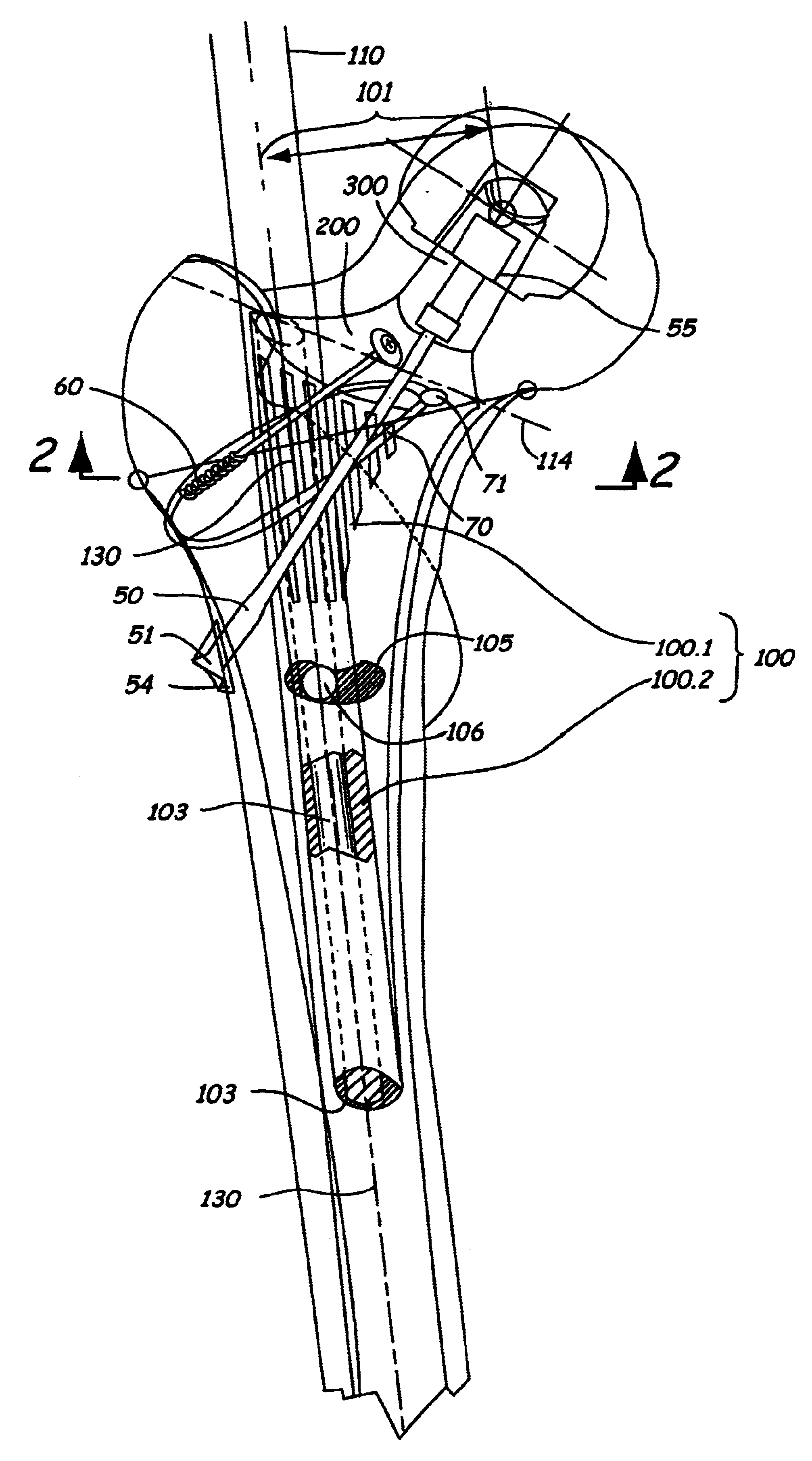
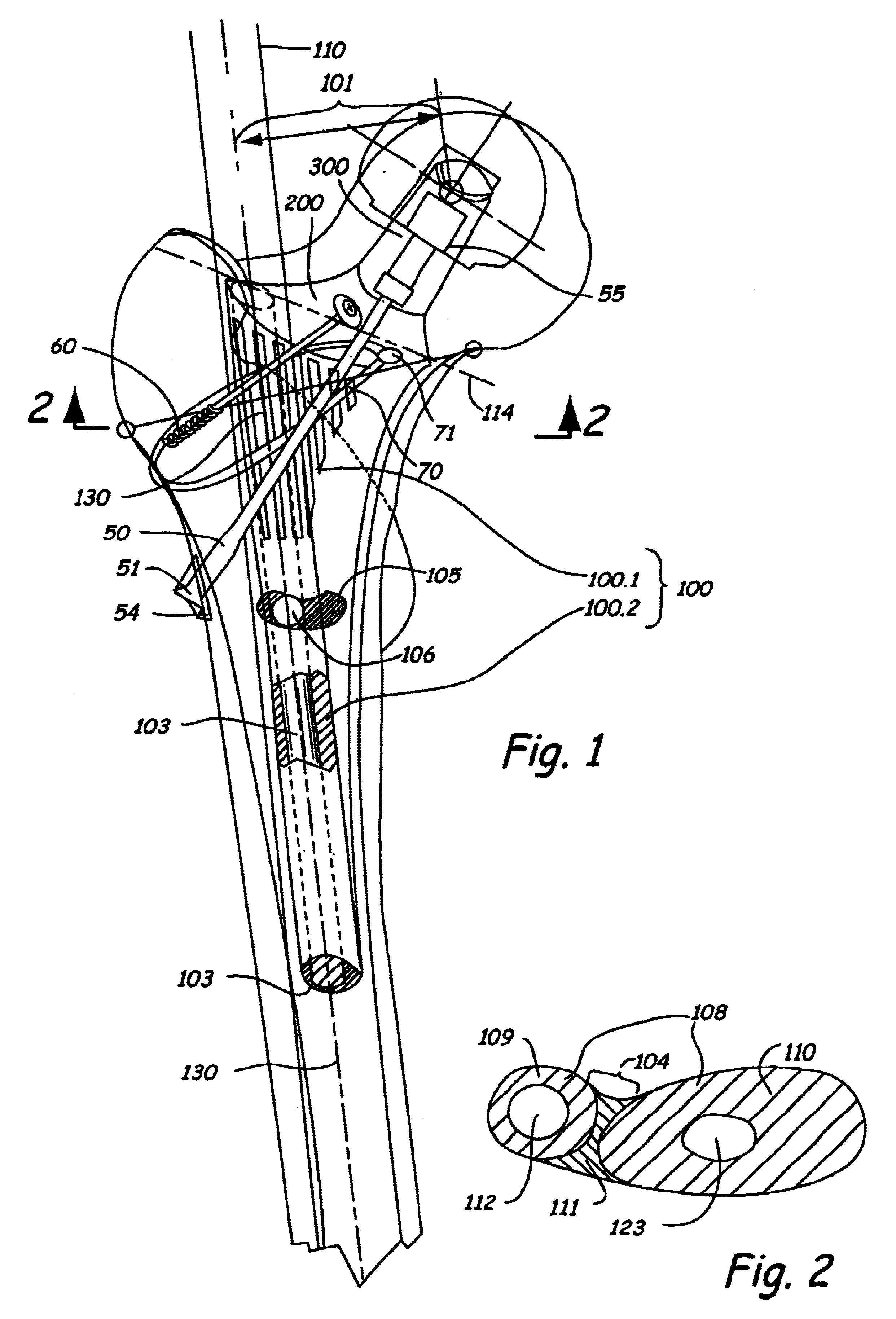
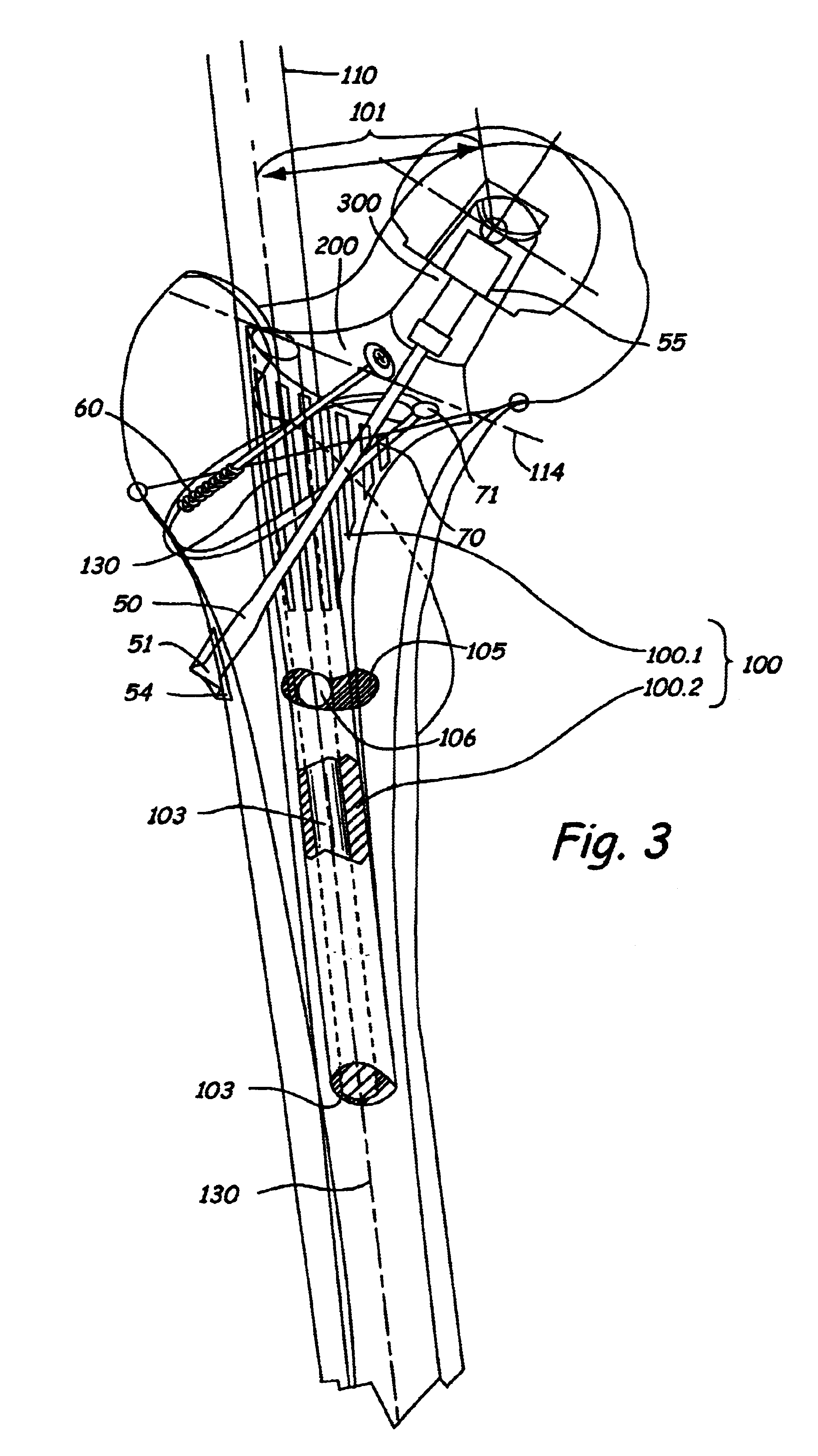
After making absolutely sure the diagnosis is loosening of the implanted hip prosthesis, the joint is exposed via the old access incision. The scar tissue is carefully removed, the joint is dislocated or separated from the femur shaft generally along plane 114, and the old, loose femur shaft is removed. Usually the old shaft can simply be pulled out; in a rare case, an instrument needs to be used to hammer it out. The old bone cement and connective tissue in the femur canal are then carefully removed. An ultrasonic titanium chisel can be very useful in this procedure.

The bone channel, or femur canal from which the connective tissue has been removed, is rinsed carefully using a jet lavage, and the bony structure is then reconstructed. To do this, tissue bank bone is ground up in a mill, and this "morcellized" bone is mixed in a 50:50 ratio with a shell-shaped bone ceramic used as the granulate--for example: Synthacer.RTM.--and it is then forced up against the walls in the intermedull...


PUM


Abstract

A modular prosthesis for replacement of hip joints has a shaft that fits into the femur canal to replace a previous prosthesis, which is made up of sections aligned and held on a cylinder that extends through the sections. In this matter, the length of the shaft can be changed to insure that the shaft will be aligned with bone sections that have not been damaged from the previous prosthesis. The shaft includes a shoulder segment adjacent the proximal end of the femur to attach to ball or head prosthesis using tension carrying screws or elements.

Description

In order to restore the function of a loose artificial hip joint, various major and minor problems have to be surmounted. The major problems are the anchorage problems related to achieving stable fixation despite often large defects remaining in the bony support after the joint components have been removed. Minor problems involve filling in the defects with bone from tissue banks; this is accomplished using "morcellized bone" plastics of the appropriate size. (Lamerigts, N. M. P., 1998. Proefschrift an der katholischen Universitt Niymegen.) Once the bony support structure has been reinforced with bone from tissue banks, the corresponding joint replacement components can be cemented in.In order to use such a procedure, the bony structures must be sufficiently stable to achieve a stable overall anchorage. However, these bone structures often are no longer present, and as a result, very special demands are placed on the implant. Therefore, there is a genuine need for systems that can b...

Claims


Application Information

Patent Timeline
Patent Type & Authority Patents(United States)
IPC IPC(8): A61F2/36A61B17/84A61B17/82A61B17/68A61F2/00A61F2/30A61F2/28A61F2/46
CPCA61F2/36A61B17/82A61B17/842A61F2/30739A61F2/367A61F2/3672A61F2/3676A61F2002/2835A61F2002/30112A61F2002/30133A61F2002/30224A61F2002/30233A61F2002/30329A61F2002/30332A61F2002/30604A61F2002/30616A61F2002/3069A61F2002/30794A61F2002/30815A61F2002/3611A61F2002/3625A61F2002/3627A61F2002/3647A61F2002/365A61F2002/3684A61F2002/3694A61F2002/4602A61F2002/4631A61F2002/4685A61F2220/0025A61F2220/0033A61F2230/0004A61F2230/0015A61F2230/0069A61F2310/00017A61F2310/00023A61F2310/00029A61F2310/00131A61F2002/30813A61F2002/3079A61F2002/368A61F2/4601
Inventor DRAENERT, KLAUS
Owner THURGAUER KANTONALBANK A CHARTERED IN & EXISTING UNDER THE LAWS OF SWITZERLAND THAT MAINTAINS ITS PRINCIPAL OFFICES AT
Why Eureka
Try Eureka