System and Method For Safely Flying Unmanned Aerial Vehicles in Civilian Airspace

Inactive Publication Date: 2008-02-07
MARGOLIN JED
View PDF4 Cites 128 Cited by
  • Summary
  • Abstract
  • Description
  • Claims
  • Application Information

AI Technical Summary

Benefits of technology

[0033] Synthetic Vision may be enhanced by combining and/or overlaying it with the video from one or more video or infrared cameras or from synthetic aperture radar.
[0034] The method described does not require material changes in the present air contr

Problems solved by technology

The current method for accomplishing this is to place restrictions on all other traffic in an air corridor representing the

Method used


Image

  • System and Method For Safely Flying Unmanned Aerial Vehicles in Civilian Airspace
  • System and Method For Safely Flying Unmanned Aerial Vehicles in Civilian Airspace
  • System and Method For Safely Flying Unmanned Aerial Vehicles in Civilian Airspace

Examples


Embodiment Construction

[0073] In the following description, numerous specific details are set forth to provide a thorough understanding of the invention. However, it is understood that the invention may be practiced without these specific details. In other instances well-known circuits, structures, and techniques have not been shown in detail in order not to obscure the invention.

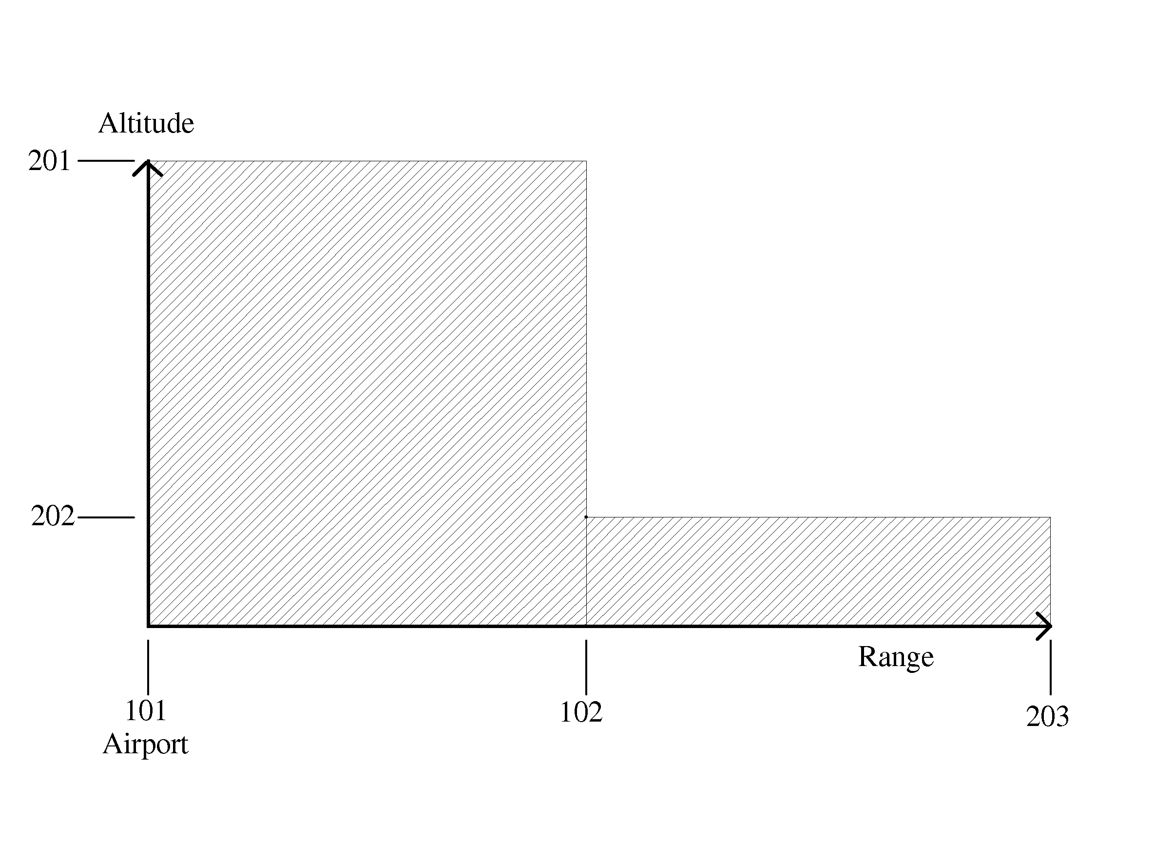
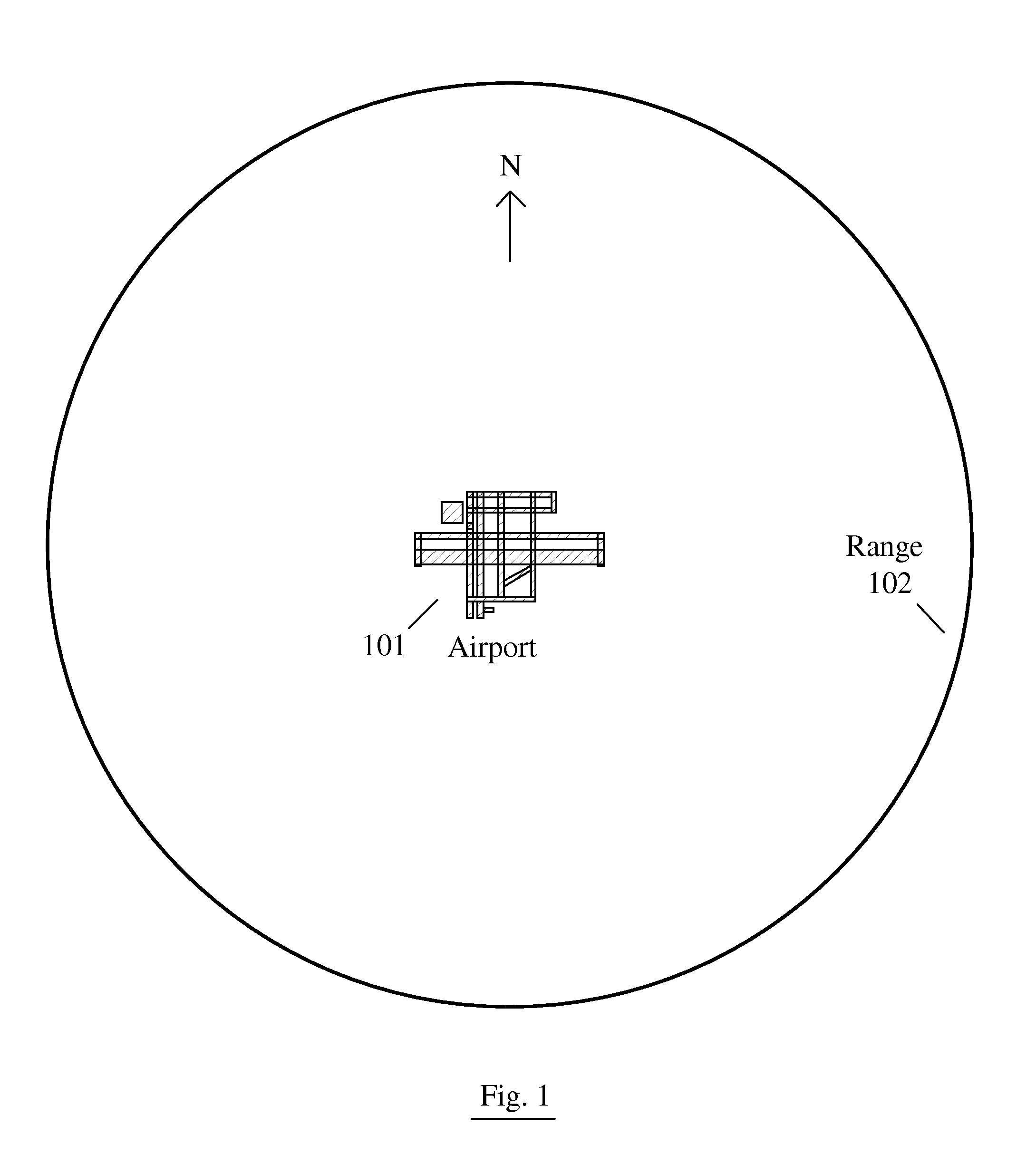
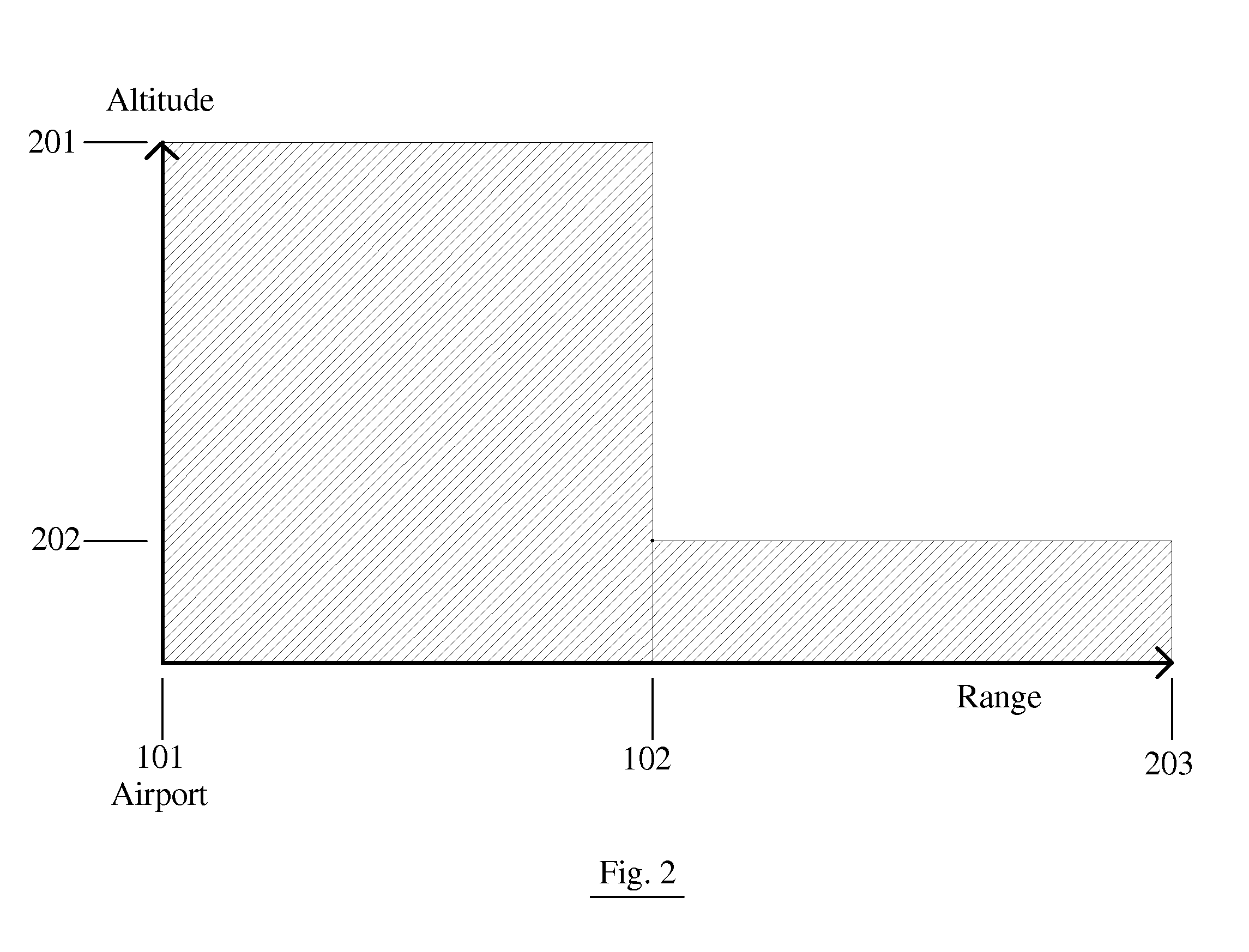
[0074]FIG. 1 shows a Distance Range 102 around Airport 101. While a circular area is shown for convenience any area whose shape can be defined may be used such as a square, rectangle, or other polygon. While FIG. 1 shows the area around an airport any other designated location may be specified. FIG. 2 shows an altitude profile of the airspace surrounding Airport 101. When the UAV is within Distance Range 102 of Airport 101 at an altitude below Selected Altitude 201 the UAV must be flown by a remote pilot using a Synthetic Vision System such as the one taught by U.S. Pat. No. 5,904,724 Method and apparatus for remotely piloting a...


PUM


Abstract

A system and method for safely flying an unmanned aerial vehicle (UAV), unmanned combat aerial vehicle (UCAV), or remotely piloted vehicle (RPV) in civilian airspace uses a remotely located pilot to control the aircraft using a synthetic vision system during at least selected phases of the flight such as during take-offs and landings.

Description

CROSS REFERENCES TO RELATED APPLICATIONS [0001] This application claims the benefit of U.S. Provisional Application No. 60 / 745,111 filed on Apr. 19, 2006.BACKGROUND OF THE INVENTION [0002] 1. Field of Invention [0003] This invention relates to the field of remotely piloted vehicles (RPVs) and unmanned aerial vehicles (UAVs). RPV is an older term for UAV. UCAV shall mean “Unmanned Combat Aerial Vehicle.” UCAV is also sometimes defined as an “Uninhabited Combat Aerial Vehicle.” UCAV is a UAV that is intended for use in combat. UAS means “Unmanned Aerial System.” UCAS means “Unmanned Combat Air System.” ROA means “Remotely Operated Aircraft.” The characteristics all these vehicles have in common is that there is no human pilot onboard and although they may be operated autonomously they can also be controlled by a remotely located operator or pilot. The term UAV shall be used as a generic term for such vehicles. “Synthetic Vision” is the current term for three dimensional projected imag...

Claims


Application Information

Patent Timeline
IPC IPC(8): G05D1/00G06F17/00
CPCG05D1/0044G05D1/0027
Inventor MARGOLIN, JED
Owner MARGOLIN JED
Why Eureka
Try Eureka