Oil control valve of a vehicle engine

a technology of oil control valve and vehicle engine, which is applied in the direction of valve drive, non-mechanical valve, machine/engine, etc., can solve the problems of increased deterioration speed easy deterioration of oil control valve, and disadvantage in low or high speed regions, so as to reduce the damage of oil control valve and improve the responsiveness

Inactive Publication Date: 2008-02-14
HYUNDAI MOTOR CO LTD
View PDF2 Cites 6 Cited by
  • Summary
  • Abstract
  • Description
  • Claims
  • Application Information

AI Technical Summary

Benefits of technology

[0011]The present invention provides an oil control valve that minimizes dama

Problems solved by technology

Valve overlap is advantageous in common regions while it is disadvantageous in low or high speed regions.
However, since a conventional oil control valve is located at a cylinder head in a lower part of a cam cap, it may be directly exposed to heat radiated from a combustion chamber.
Therefore, an oil control valve can be easily deter

Method used


Image

  • Oil control valve of a vehicle engine
  • Oil control valve of a vehicle engine
  • Oil control valve of a vehicle engine

Examples


Embodiment Construction

[0023]The present invention will be described more fully hereinafter with reference to the accompanying drawings, in which exemplary embodiments of the invention are shown. As those skilled in the art would realize, the described embodiments may be modified in various different ways, all without departing from the spirit or scope of the present invention.

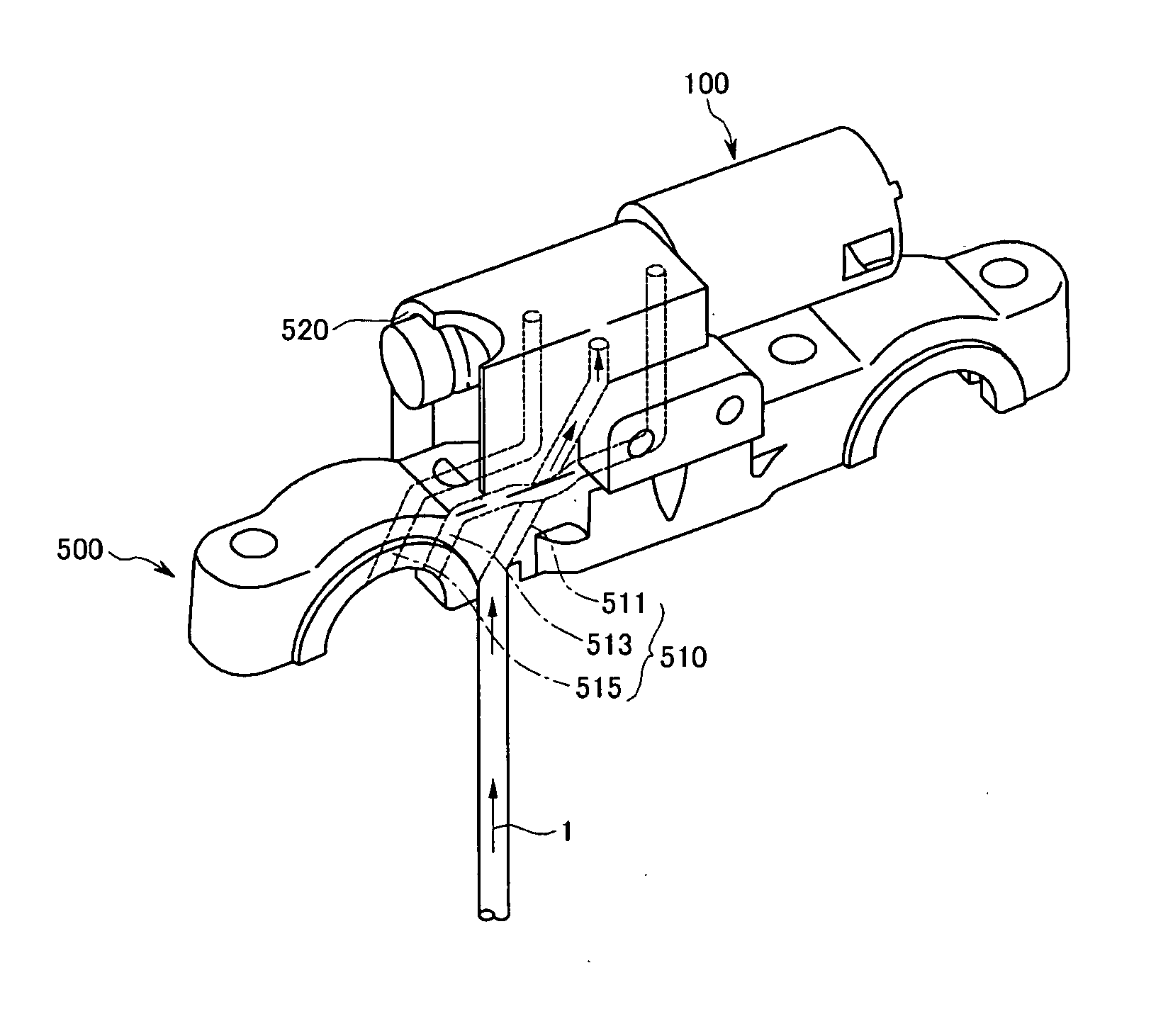
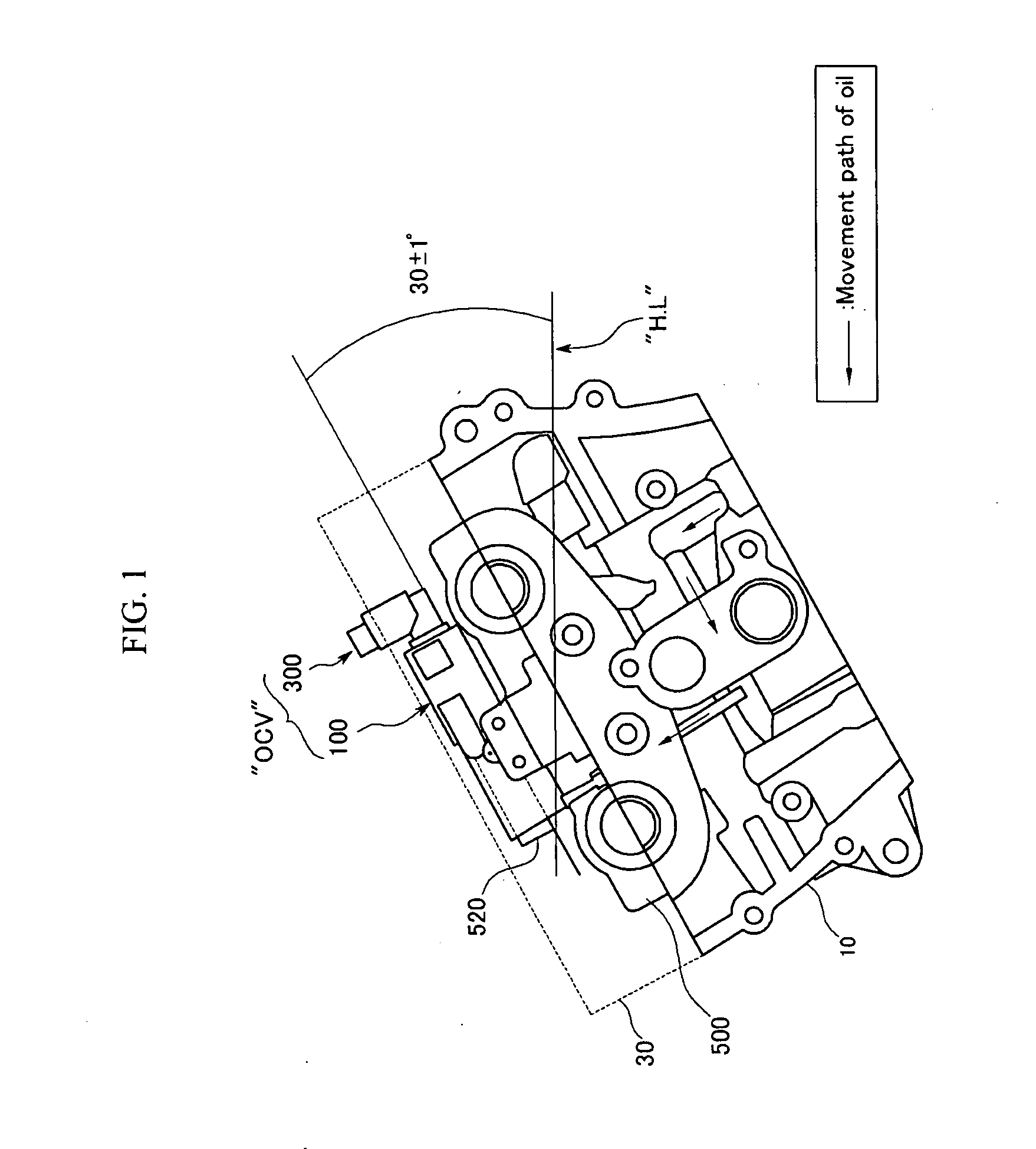
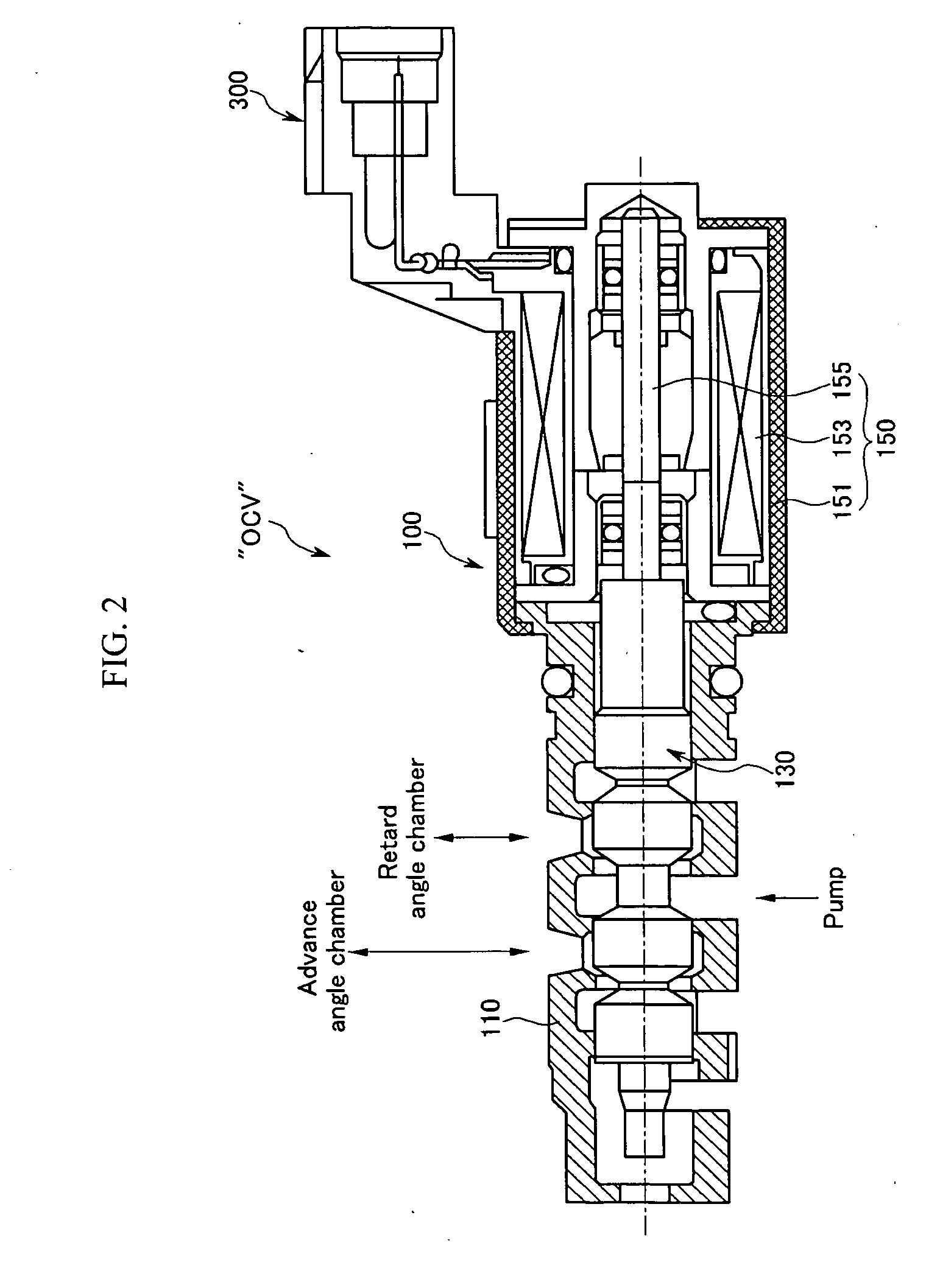
[0024]As shown in FIG. 1, an oil control valve (OCV) according to an exemplary embodiment of the present invention includes an operation unit 100 and a connector 300.

[0025]The operation unit 100 changes a path of oil flowing into a continuously variable valve timing unit (not shown). The connector 300 supplies the operation unit 100 with power.

[0026]The operation unit 100 is engaged to the upper part of the cam cap 500 by a mounter 520. Therefore, since the operation unit 100 is located away from a combustion chamber (not shown) of a cylinder head 10, and from an exhaust manifold (not shown), degradation of the oil control valve (OC...


PUM


Abstract

An oil control valve includes an operation unit at an upper part of a cam cap and an inner part of a head cover that changes a path of fluid into a continuously variable valve timing unit, and a connector that supplies power to the operation unit. The operation unit may include a sleeve, a valve movably located at the sleeve that directly changes the path of the fluid, and a driving portion that drives the valve. The connector may be located at the driving portion and exposed to outside the head cover. The driving portion may be higher than the sleeve, and may be inclined by approximately 30° with respect to a horizontal line. A hydraulic line may further be provided in the cam cap to guide the fluid into chambers of the continuously variable valve timing unit.

Description

CROSS-REFERENCE TO RELATED APPLICATION[0001]This application claims priority to and the benefit of Korean Patent Application No. 10-2006-0075642 filed in the Korean Intellectual Property Office on Aug. 10, 2006, the entire contents of which are incorporated herein by reference.BACKGROUND OF THE INVENTION[0002](a) Field of the Invention[0003]The present invention relates to an oil control valve of a vehicle engine.[0004](b) Description of the Related Art[0005]Generally, an oil control valve of a vehicle engine is a component of a continuously variable valve timing (CVVT) device. The oil control valve changes a path of engine oil supplied from a hydraulic pump to the CVVT device under control of an engine control unit, and adjusts opening and closing times of an exhaust or intake valve.[0006]Such an oil control valve includes a connector, a plunger with a permanent magnet, a coil, a spool connected to the plunger, and a sleeve. When the connector is supplied with power, a magnetic fie...

Claims


Application Information

Patent Timeline
IPC IPC(8): F01L9/02F01L1/34F01L1/02
CPCF01L1/3442F01L2001/028F16K11/07F01L2001/34426F01L2001/3443F01L2001/0476F01L1/34F01M1/16
Inventor KIM, WOONGJUNG, JAE-HO
Owner HYUNDAI MOTOR CO LTD
Why Eureka
Try Eureka