Damping Device with Power-Assisted Deceleration and Use Thereof for the Damping of the Retractable Steering Column of a Motor Vehicle

a technology of damping device and steering column, which is applied in the direction of shock absorbers, vibration dampers, springs/dampers, etc., can solve problems such as valve closing

Inactive Publication Date: 2008-02-14
CONSEIL & TECH SARL
View PDF0 Cites 8 Cited by
  • Summary
  • Abstract
  • Description
  • Claims
  • Application Information

AI Technical Summary

Benefits of technology

[0014] The object of the present invention is to cope with the various above-mentioned disadvantages by providing a damping device with power-assisted deceleration allowing achieving a constant or nearly constant deceler

Problems solved by technology

This flow results into reducing deceleration, w

Method used


Image

  • Damping Device with Power-Assisted Deceleration and Use Thereof for the Damping of the Retractable Steering Column of a Motor Vehicle
  • Damping Device with Power-Assisted Deceleration and Use Thereof for the Damping of the Retractable Steering Column of a Motor Vehicle
  • Damping Device with Power-Assisted Deceleration and Use Thereof for the Damping of the Retractable Steering Column of a Motor Vehicle

Examples


Embodiment Construction

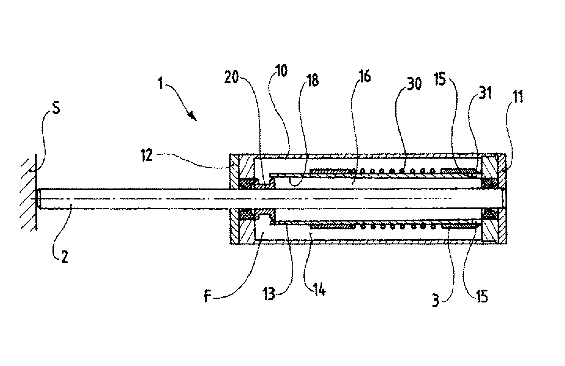
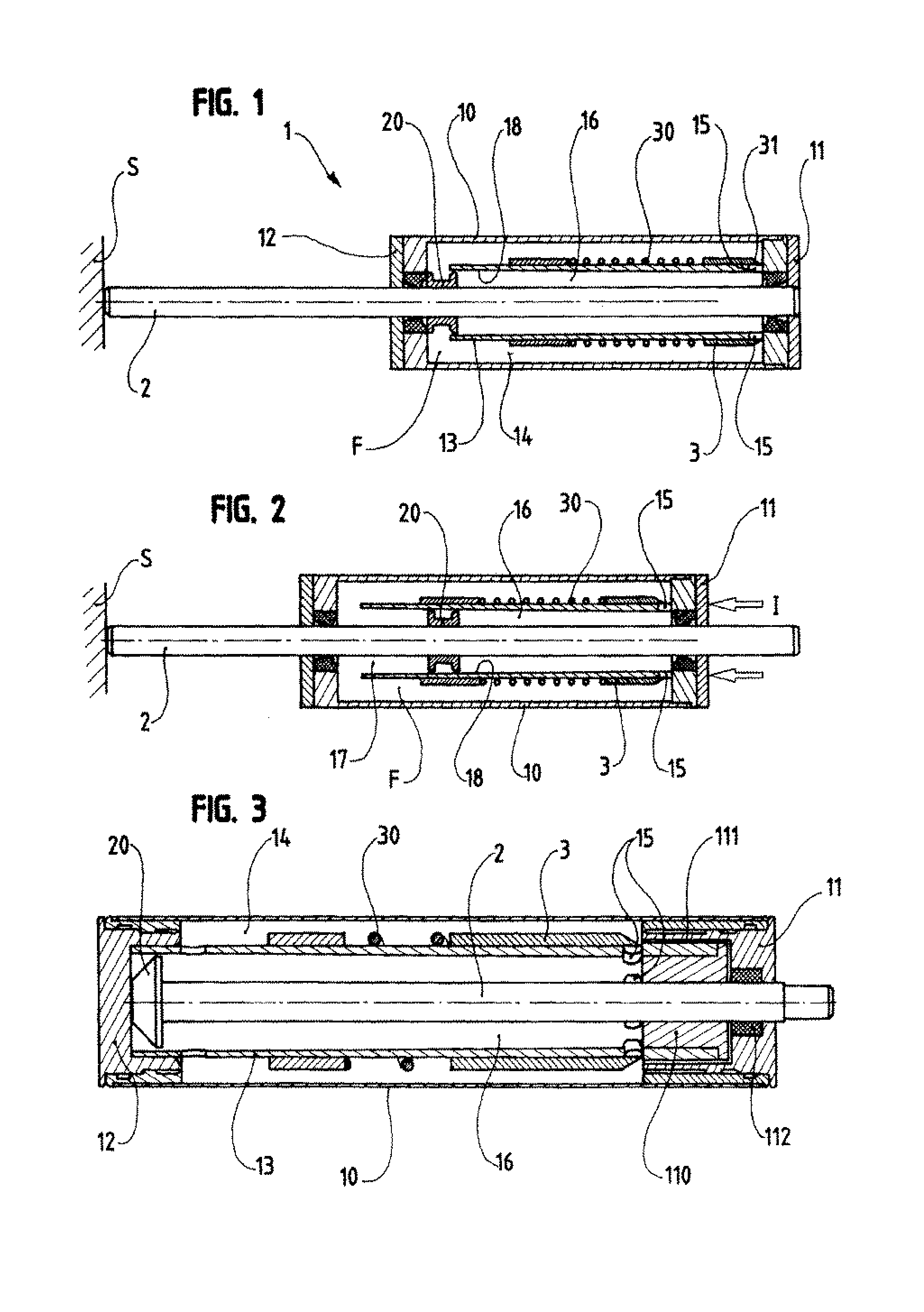
[0037] When referring to FIGS. 1 and 2, one can see a first embodiment 1 of a damping device with power-assisted deceleration according to the invention.

[0038] It includes a tubular body 10 closed at its two ends by two flanges 11 and 12, filled with a hydraulic fluid F, and which contains a tubular jacket 13 of reduced transverse dimensions so as to create a peripheral space 14.

[0039] The ends of the tubular jacket 13 are formed so as to allow a communication of the peripheral space 14 with the interior of the tubular jacket 13, which, on the side of the flange 11, occurs through radial holes 15.

[0040] Through the body 10 axially passes a rod 2 on which is clamped a piston 20 capable of longitudinally evolving in the tubular jacket 13 according to the displacement of the rod 2. The piston 20 divides the tubular jacket 13 into two chambers, a compression chamber or first chamber 16 on the side of the flange 11 and the holes 15, and a second chamber 17 on the other side, more part...


PUM


Abstract

The invention relates to a damping device with power-assisted deceleration, which is intended to be used in the field of hydraulic shock dampers. The invention includes a sealed body filled with a hydraulic fluid and a piston mounted in the sealed body. The piston is connected to a rod axially movable outside the body. The rod and the body are arranged such that, while one is solidly connected to a support, an impact in relation to the other causes axial movement of the piston and compression of the fluid in a chamber. The invention also includes a flow mechanism for the hydraulic fluid to be released from the chamber and an element which can move axially inside the body to form a check valve that can seal the flow mechanism when pushed back in the opposite direction to that of the impact by an elastic device.

Description

BACKGROUND OF THE INVENTION [0001] (1) Field of the Invention [0002] The present invention relates to a damping device with power-assisted deceleration, for use in the field of the hydraulic shock absorbers. [0003] (2) Description of the Prior Art [0004] The hydraulic shock absorbers presently well-known allow controlling the stopping of an impacted object through causing a nearly constant deceleration of the latter. However, for a given design and size of the shock absorber, the level of deceleration varies according to the mass of said object, as well as according to its speed of impact. [0005] Depending on the field of application involved, this feature can constitute a limit for the implementation of such a damping device. [0006] This is the case, not restrictively, in the field of the elevators, the anti-collision systems, car building and namely as regards the steering columns. [0007] Indeed, it is known that the steering wheel is a traumatizing obstacle for the driver in the ...

Claims


Application Information

Patent Timeline
IPC IPC(8): F16F9/48F16F9/512F16F9/49
CPCF16F9/48F16F9/512F16F9/49
Inventor VALEMBOIS, GUY
Owner CONSEIL & TECH SARL
Why Eureka
Try Eureka