
Equipment and process for applying an external structural weld to piping and similarly shaped pressure boundary components

Active Publication Date: 2008-02-14
AZZ WSI
View PDF11 Cites 5 Cited by
  • Summary
  • Abstract
  • Description
  • Claims
  • Application Information

AI Technical Summary

Benefits of technology

[0010]In an additional embodiment, the disclosed apparatus and method permits use of welding equipment to apply a weld overlay on piping systems without the need to attach to the member that is to be welded.

Problems solved by technology

Pipes, fittings, and nozzles are subject to degradation or material failure in a mechanical system.

Method used


Image

  • Equipment and process for applying an external structural weld to piping and similarly shaped pressure boundary components
  • Equipment and process for applying an external structural weld to piping and similarly shaped pressure boundary components
  • Equipment and process for applying an external structural weld to piping and similarly shaped pressure boundary components

Examples


Embodiment Construction

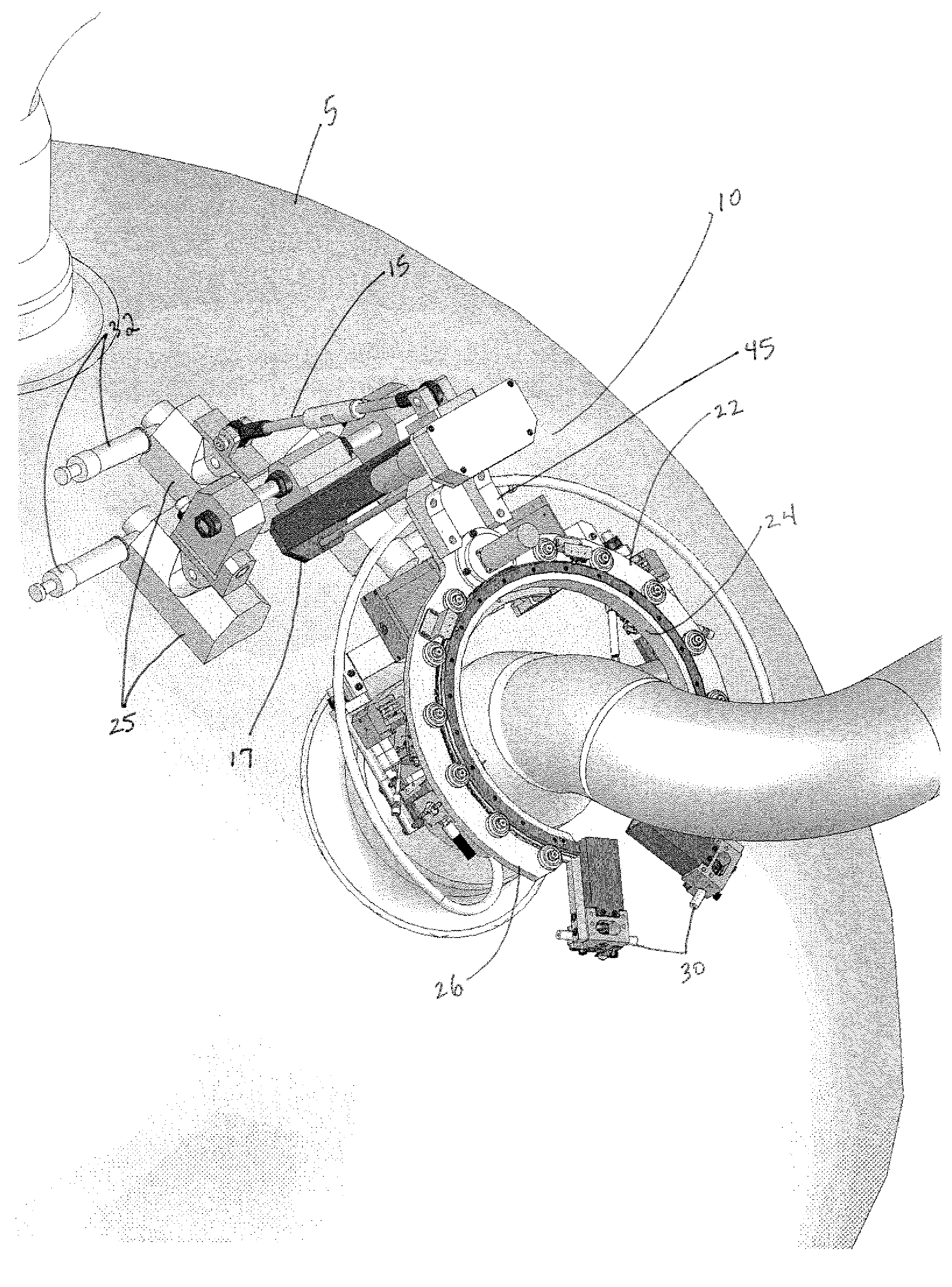
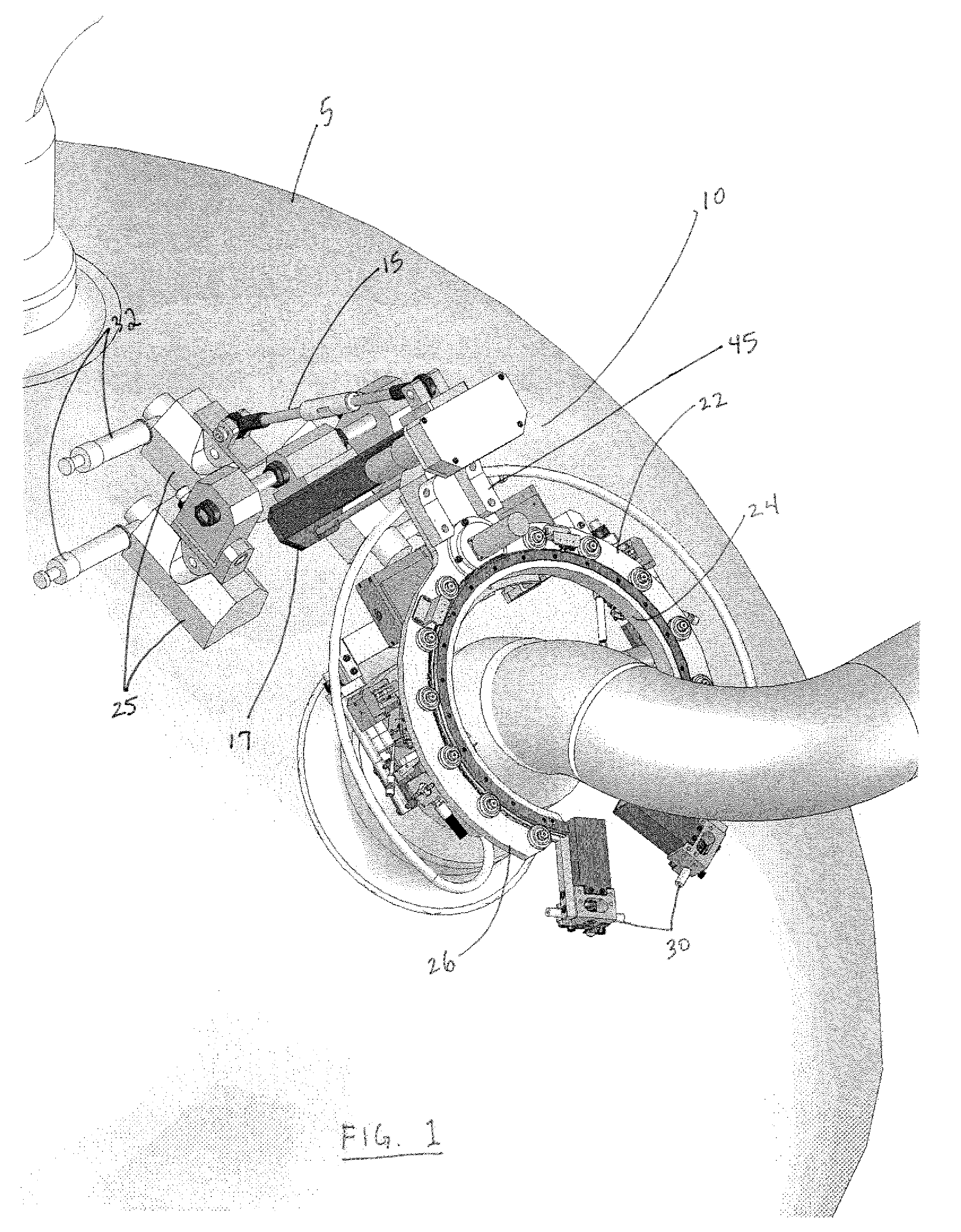
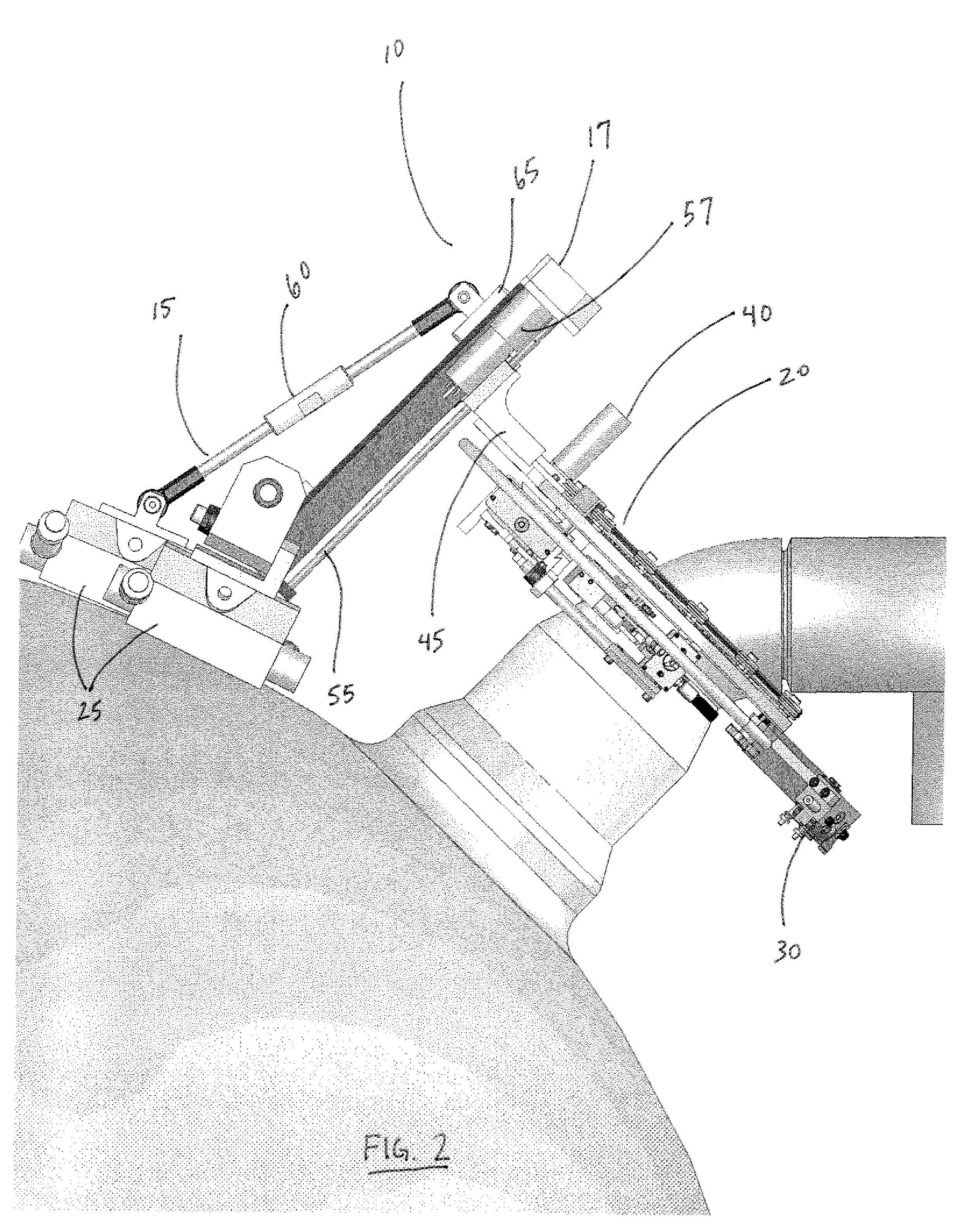
[0020]In one embodiment, an apparatus 10 for applying a weld overlay to a nozzle or piping spool of complex configuration is disclosed. In one example, the apparatus 10 comprises a mounting assembly 15, a travel guide 17 and a head assembly 20. The head assembly 20 includes a plurality of orbital weld heads for applying a weld overlay to a nozzle, piping or fitting. In another example, the apparatus 10 provides a new assembly and process that allows an easily mountable system that may operate in a smaller area and avoiding interferences and inability to mount the system. In yet another example, the welding equipment includes a plurality of different drive mechanisms to allow for application of a weld overlay on a potentially irregular surface.

[0021]In addition to application of a weld overlay, the welding apparatus equipment system 10 may be utilized for several other applications. For example, the system could be utilized to weld piping joints for similarly complex configurations o...


PUM

PropertyMeasurementUnit
Angleaaaaaaaaaa
Heightaaaaaaaaaa
Dynamicaaaaaaaaaa

Abstract

An apparatus and / or process for applying a weld overlay to a nozzle or piping spool of complex configuration is disclosed. In an exemplary embodiment, the welding apparatus comprises a mounting assembly having a plurality of magnetic foot pads, a tension support rod attached at one end to one of the magnetic foot pads, an upper attachment pad at the opposite end of the rod, and a bottom attachment pad attached to at least one other magnetic foot pad; a travel guide, the travel guide attached to the upper attachment pad at one end and the bottom attachment pad at the other end; and a head assembly attached to the travel guide, the head assembly having: i) a track ring assembly having an inner ring and an outer ring, ii.) at least two opposed weld heads attached to the inner track ring, iii.) at least one movable wire feed drive mechanism on the track ring, and iv.) a drive mechanism located on the outer ring of the track ring, the drive mechanism adapted to permit rotation of the inner ring and the weld heads around the component to be welded.

Description

BACKGROUND[0001]1. Technical Field[0002]The present invention relates to a system and / or method for overlaying metal piping with a weld overlay. More specifically, a process and / or apparatus for applying a weld overlay to piping, fittings or nozzles utilizing a welding apparatus is disclosed.[0003]2. General Background[0004]Pipes, fittings, and nozzles are subject to degradation or material failure in a mechanical system. To prevent or fix this problem, weld overlays are often placed over theses areas to either repair damage or to prevent failure of the original boundary materials with pre-emptive reinforcement. Applying a weld overlay to a structural component will protect the integrity of the mechanical system.[0005]Conventional orbital welding equipment systems that rely on either single or double weld heads typically require vertical-up application of a weld overlay that applies a weld bead only on one side of the pipe. After the first weld bead is placed on approximately half (...

Claims


Application Information

Patent Timeline
IPC IPC(8): B23K9/12
CPCB23K9/048
Inventor AMADOR, PEDROSCULLEY, JAMESMADILL, JEFFREYSTONER, JACKPARKER, DIXONPOWER, CASEY A.
Owner AZZ WSI
Learn More