

Connector of Flexible Pipe
- Summary
- Abstract
- Description
- Claims
- Application Information
AI Technical Summary
Benefits of technology
Problems solved by technology
Method used
Image

Examples
first embodiment
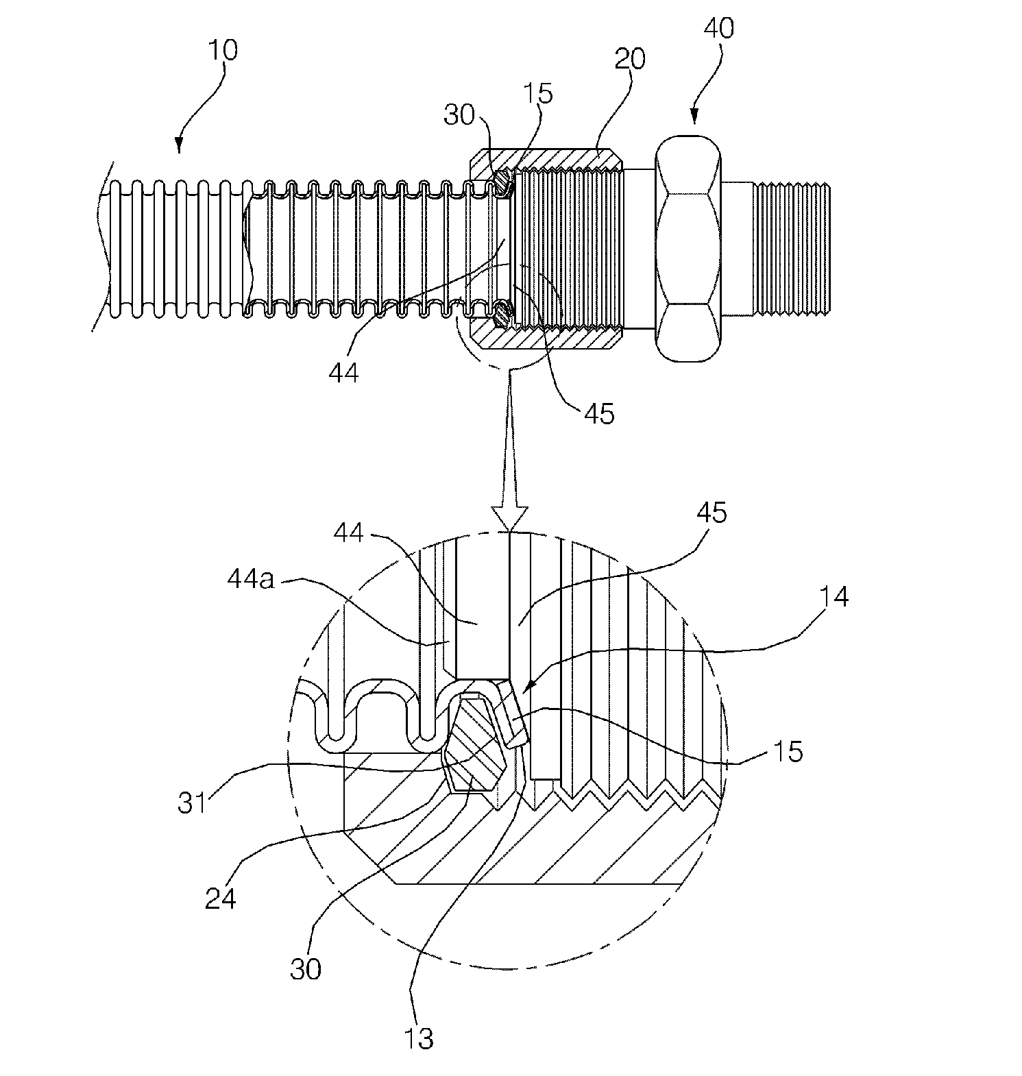
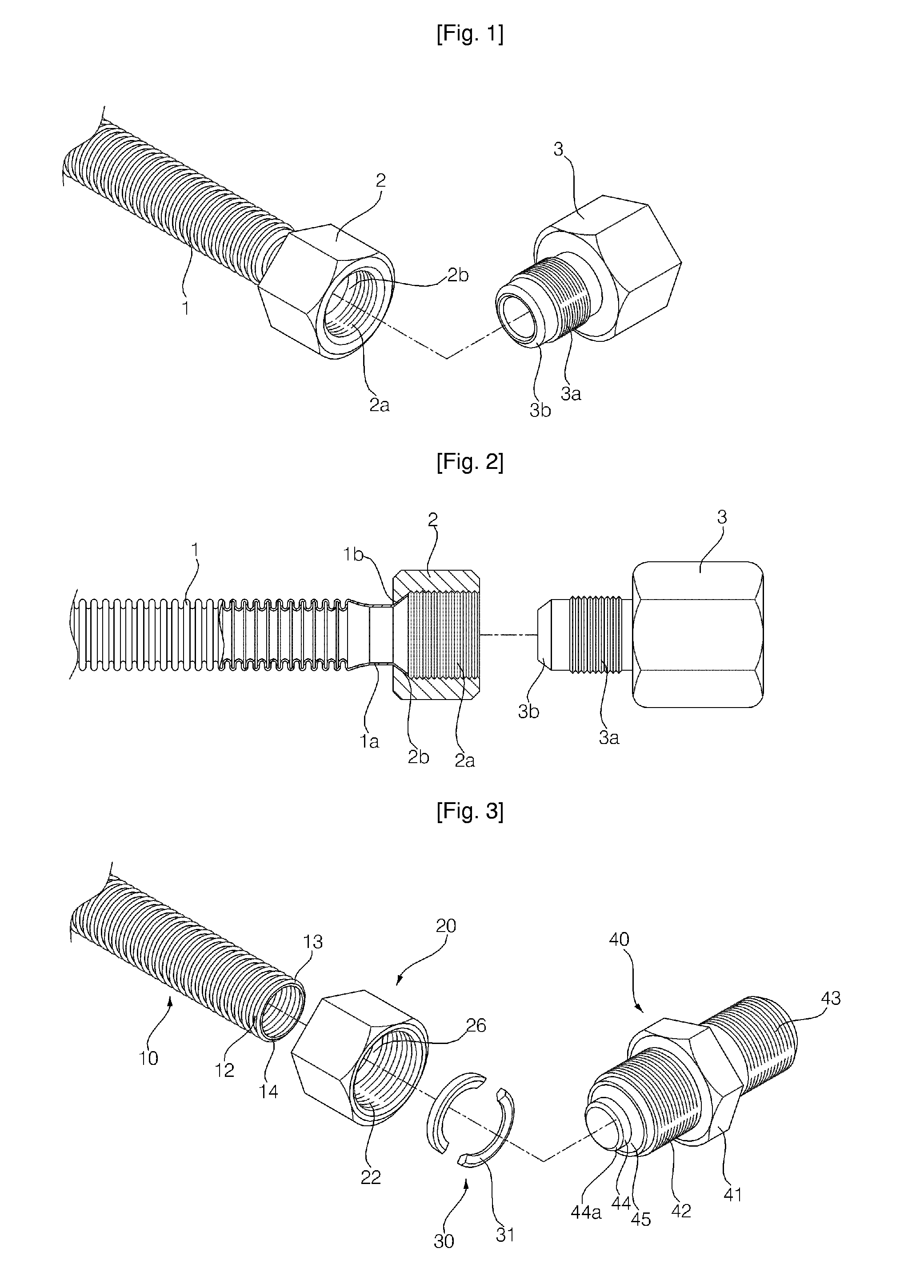
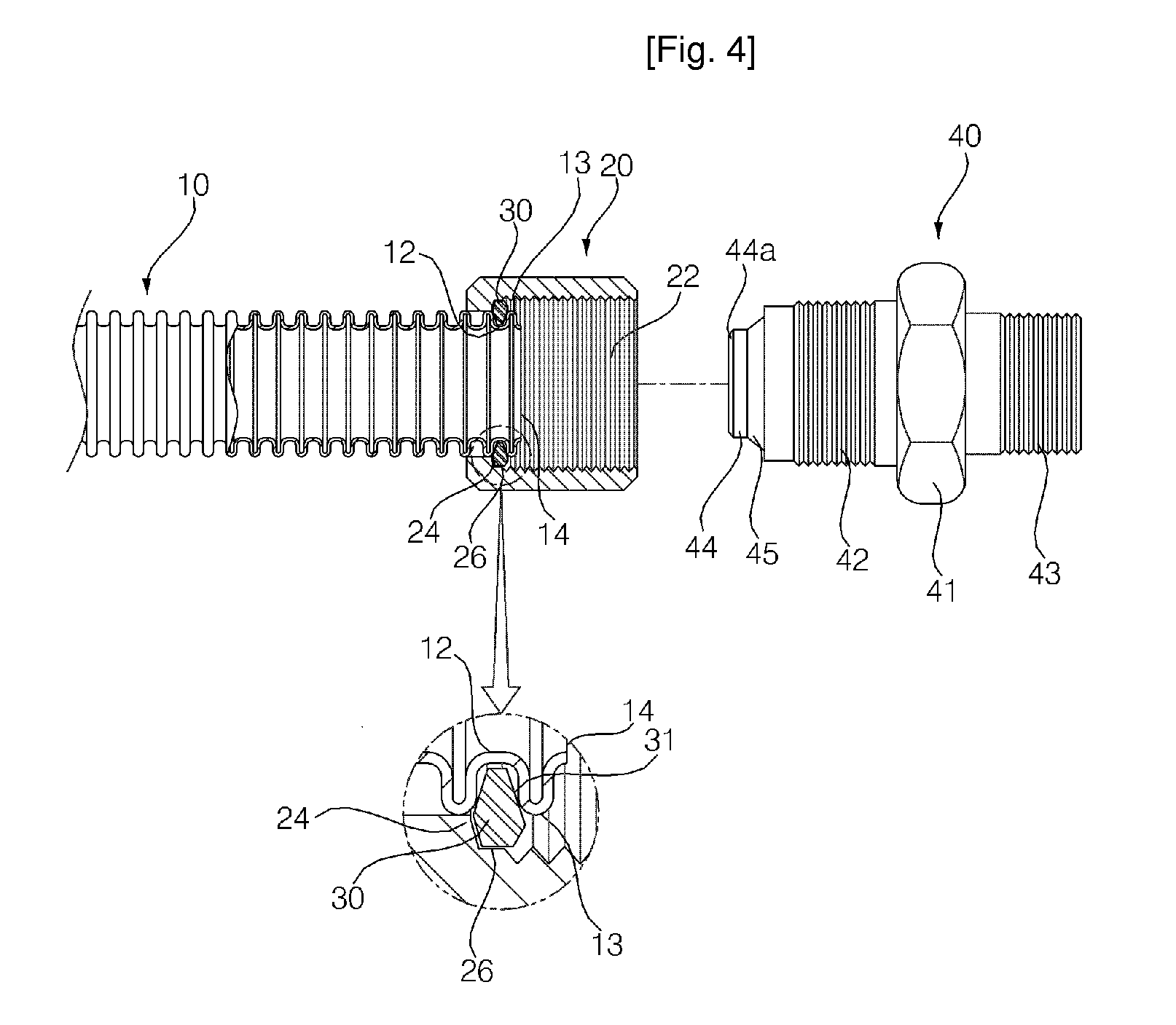
[0032]FIG. 3 is an exploded perspective view showing a connector of flexible pipe according to the present invention, FIG. 4 is a front view, partially in section, in which a socket tube is shown prior to being coupled in the connector of flexible pipe shown in FIG. 3 and FIG. 5 is a front view, partially in section, in which the socket tube is shown after being coupled in the connector of flexible pipe shown in FIG. 3.
[0033] As shown in FIG. 3 and FIG. 4, the connector of flexible pipe according to the first embodiment of the present invention comprises a tube 10 having an outer surface on which a continuous corrugation is formed; a fastening nut 20 in which the flexible pipe 10 is inserted; a latching ring 30 having an inner portion received in a valley section 12 of the flexible pipe 10 and an outer portion extruded outward for preventing the fastening nut 20 from separating from the flexible pipe 10; and a socket tube 40 contacted closely with the latching ring by a combining fo...
second embodiment
[0052]FIG. 6 is an exploded perspective view showing a connector of flexible pipe according to the present invention, FIG. 7 is a front view, partially in section, in which the socket tube is shown prior to being coupled in the connector of flexible pipe shown in FIG. 6 and FIG. 8 is a front view, partially in section, in which the socket tube is shown after being coupled in the connector of flexible pipe shown in FIG. 6.
[0053] As shown in FIG. 6, the connector of flexible pipe according to the second embodiment of the present invention comprises a tube 50 having an outer surface on which a continuous corrugation is formed; a fastening nut 60 in which the flexible pipe 50 is inserted, the fastening nut having a latching section 64 formed on an inner surface thereof; a latching ring 70 having an inner portion received in a valley section 52 of the flexible pipe 50 and an outer portion extruded outward and contacted with the latching section 64 of the fastening nut 60 for preventing t...
third embodiment
[0077]FIG. 9 is a sectional view showing a connector of flexible pipe according to the present invention.
[0078] In the third embodiment of the present invention, a sectional surface of a latching ring 70 has a linear shape and an O-ring 99 which is a sealing member is inserted between a fastening nut 60 and a flexible pipe 50 to seal insides of the fastening nut and the flexible pipe 50′
[0079] In the third embodiment of the present invention as described above, in the case that a pitch between the thread sections of the flexible pipe 50 is narrow, a thick of the latching ring 70 to be received in a valley section 52 of the flexible pipe 50 becomes remarkably narrow, and so the latching ring does not have a sufficient rigidity in the case that the latching ring has a shape and structure which are same as those of the latching ring in the aforementioned embodiments.
[0080] Accordingly, a groove section 69 is formed on an inner circumference surface of the fastening nut 60 and the O-ri...
PUM
 Abstract
Description
Claims
Application Information