Motor

Inactive Publication Date: 2008-02-14
SAMSUNG ELECTRO MECHANICS CO LTD
View PDF4 Cites 12 Cited by
  • Summary
  • Abstract
  • Description
  • Claims
  • Application Information

AI Technical Summary

Benefits of technology

[0008]An aspect of the claimed invention is to provide a motor that offers high stability and an increased sealing effect, by forming a radi

Problems solved by technology

However, in the case of a spindle motor having the conventional bearing structure, the oil in which the bearing is immersed may leak to the exterior, to degrade the performance of the motor.
When the oil is leaked, problems may occur in high-speed rotation, and abrasion may occur due to frict

Method used


Image

  • Motor
  • Motor
  • Motor

Examples


Embodiment Construction

[0032]The motor according to certain embodiments of the invention will be described below in more detail with reference to the accompanying drawings, in which those components are rendered the same reference number that are the same or are in correspondence, regardless of the figure number, and redundant explanations are omitted.

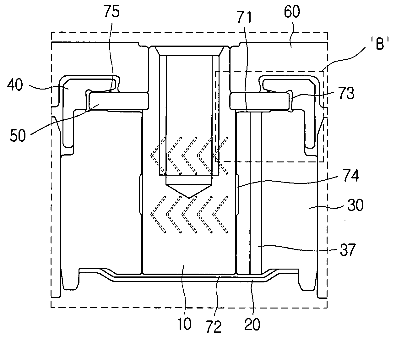
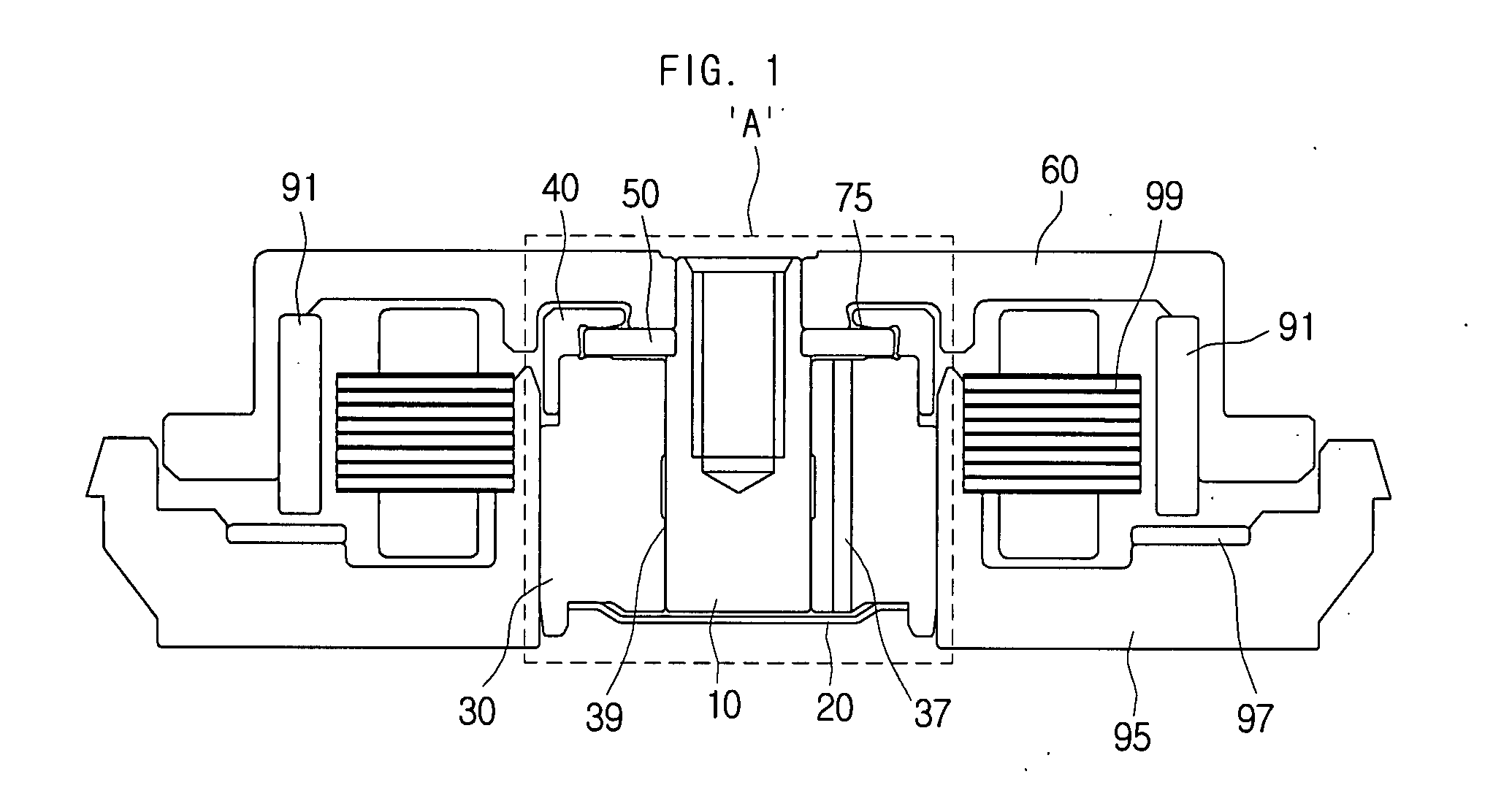
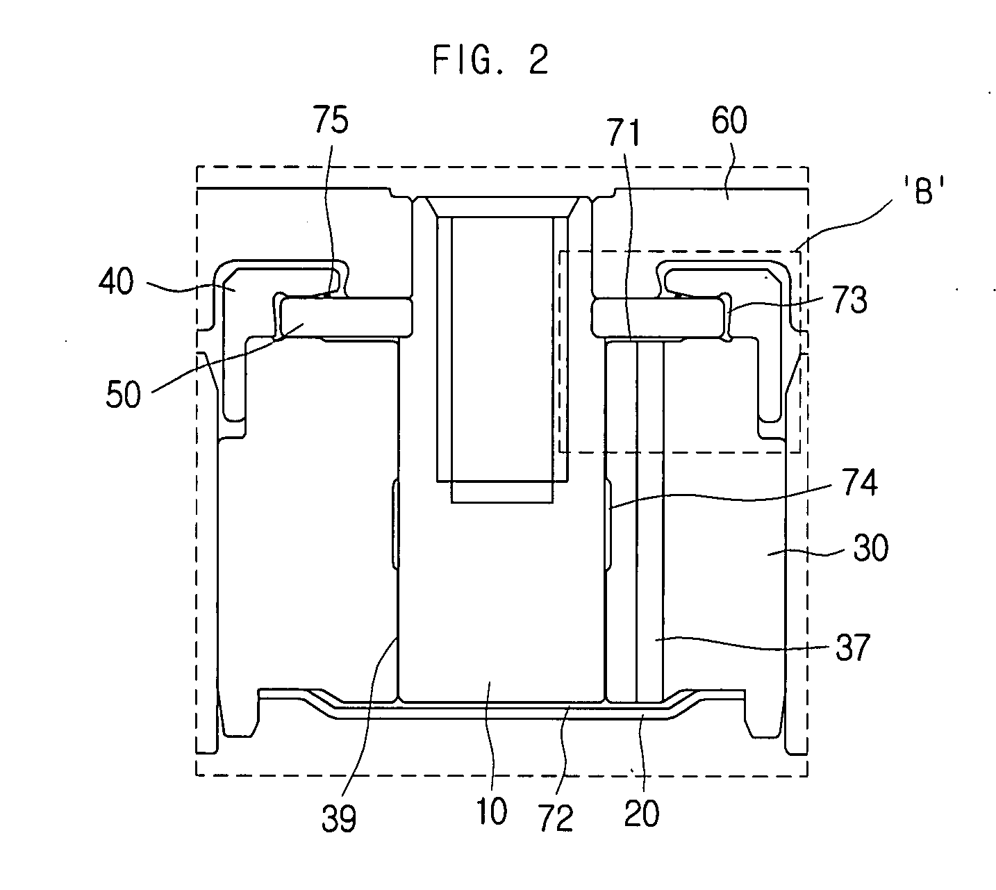
[0033]In general, a motor consists basically of a rotating member, a stationary member that supports the rotating motion of the rotating member, and a bearing placed between the rotating member and the stationary member. For example, the rotating member may be a coupled body including a shaft, a hub coupled to and rotating together with the shaft, and a plate, etc., and the stationary member may be a sleeve, etc., surrounding the shaft.

[0034]However, the rotating member and the stationary member are not determined by the components per se, but are determined by their designed functions. That is, there may be cases where the shaft is fixed and the sleeve surr...


PUM


Abstract

A motor is disclosed. The motor, which includes a stationary member, a rotating member coupled to the stationary member that rotates about an imaginary rotational axis, a plate coupled to or mounted on the rotating member to support the rotating member, a cap covering at least a portion of the plate to form a predetermined space between the plate and the cap, and fluid placed in the space between the plate and the cap, may maintain a uniform pressure in its interior to increase stability and provide an increased sealing effect.

Description

CROSS-REFERENCE TO RELATED APPLICATIONS[0001]This application claims the benefit of Korean Patent Application No. 10-2006-0074563 filed with the Korean Intellectual Property Office on Aug. 8, 2006, and to Korean Patent Application No. 10-2007-0016902 filed with the Korean Intellectual Property Office on Feb. 20, 2007, the disclosures of which are incorporated herein by reference in their entirety.BACKGROUND[0002]1. Technical Field[0003]The claimed invention relates to a motor.[0004]2. Description of the Related Art[0005]In general, the spindle motor is currently widely used in electronic products that require precision rotating devices such as projection TV's, home theater equipment, and computer drives. The spindle motor provides several advantages such as that it has a small size, thereby allowing high-speed rotation, easy precision control, and low power consumption, etc., so that its use is expected to increase well into the future.[0006]However, in the case of a spindle motor h...

Claims


Application Information

Patent Timeline
IPC IPC(8): H02K5/16H02K5/124
CPCH02K5/1675
Inventor KIM, DUCK-YOUNGLEE, TA-KYOUNG
Owner SAMSUNG ELECTRO MECHANICS CO LTD
Why Eureka
Try Eureka