Wireless electromagnetic parasitic power transfer

a technology of parasitic power transmission and wireless transmission, which is applied in the direction of measurement devices, signal systems, instruments, etc., can solve the problems of battery failure at the inopportune time, difficulty and cost of battery replacement in wireless devices that are hard to access, and battery replacemen

Active Publication Date: 2008-02-14
SECURAPLANE TECH
View PDF6 Cites 180 Cited by
  • Summary
  • Abstract
  • Description
  • Claims
  • Application Information

AI Technical Summary

Problems solved by technology

But replacing batteries in wireless devices that are hard to access can be difficult and costly.
Furthermore, batteries can fail at inopportune, unpredictable times. In applications where temporary outages of remote devices are not acceptable, batteries must be replaced preventively on a regular basis.
The problem is especially troublesome for remote RF receivers because they must be on continuously in order to be able to receive a transmission.
Although this can prolong battery life, it can reduce the utility of the remote wireless device.

Method used


Image

  • Wireless electromagnetic parasitic power transfer
  • Wireless electromagnetic parasitic power transfer
  • Wireless electromagnetic parasitic power transfer

Examples


Embodiment Construction

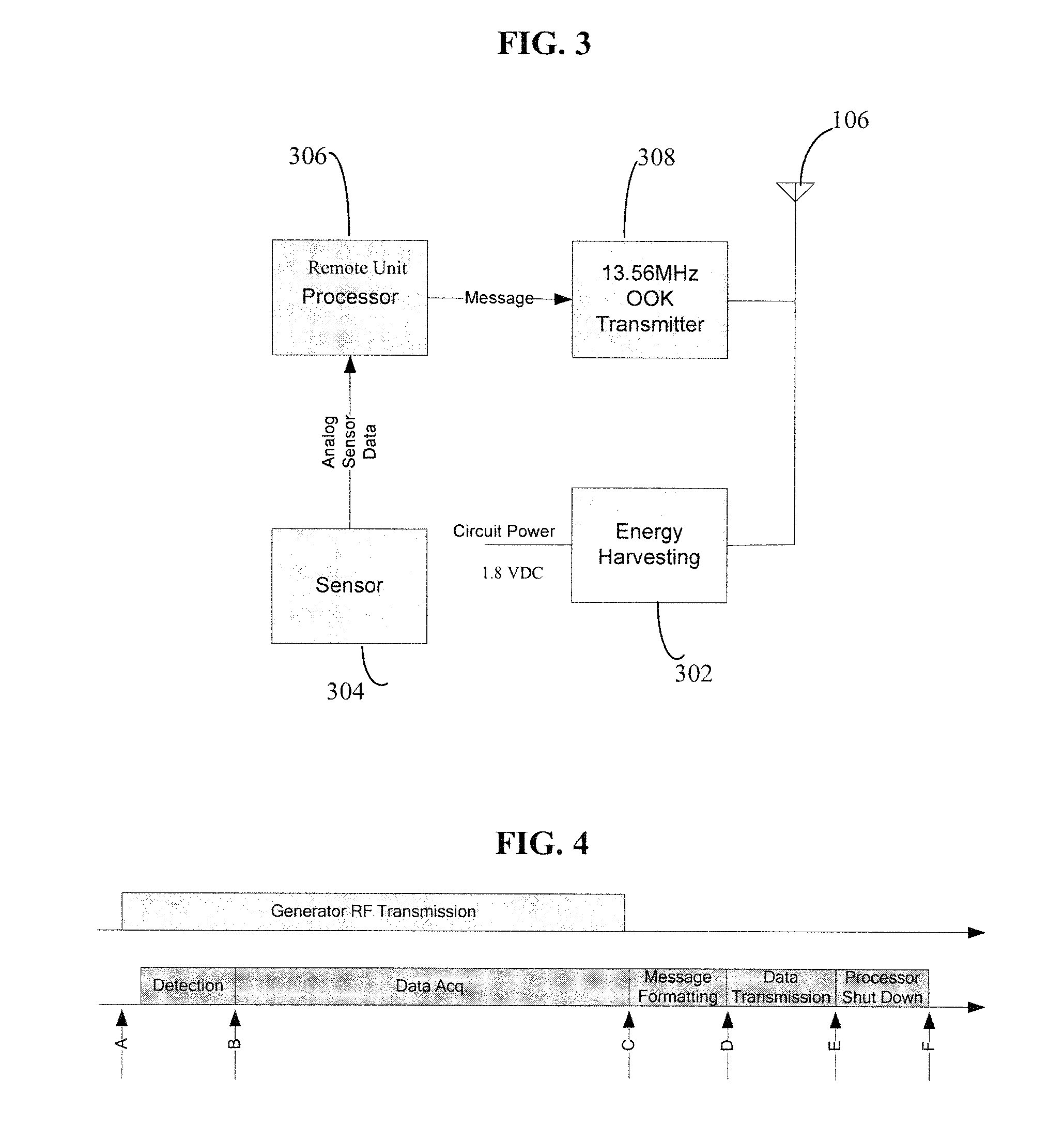
[0015] The described embodiment is a system for transmitting power via RF parasitic power transfer from a transmitting coil connected to a master unit to a receiving coil connected to a wireless remote unit. The master unit is powered by an external source, but the remote unit has no source of power other than what it receives via electromagnetic coupling with the master unit. The remote unit includes a sensor for measuring data of interest, a processor in communication with the sensor for controlling the sensor, formatting the message, and controlling data transmission, and a transmitter for sending the acquired data back to the master unit or to another receiving unit.

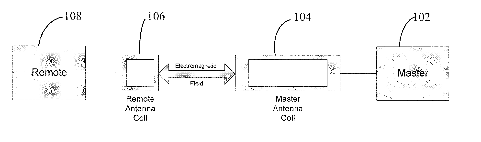
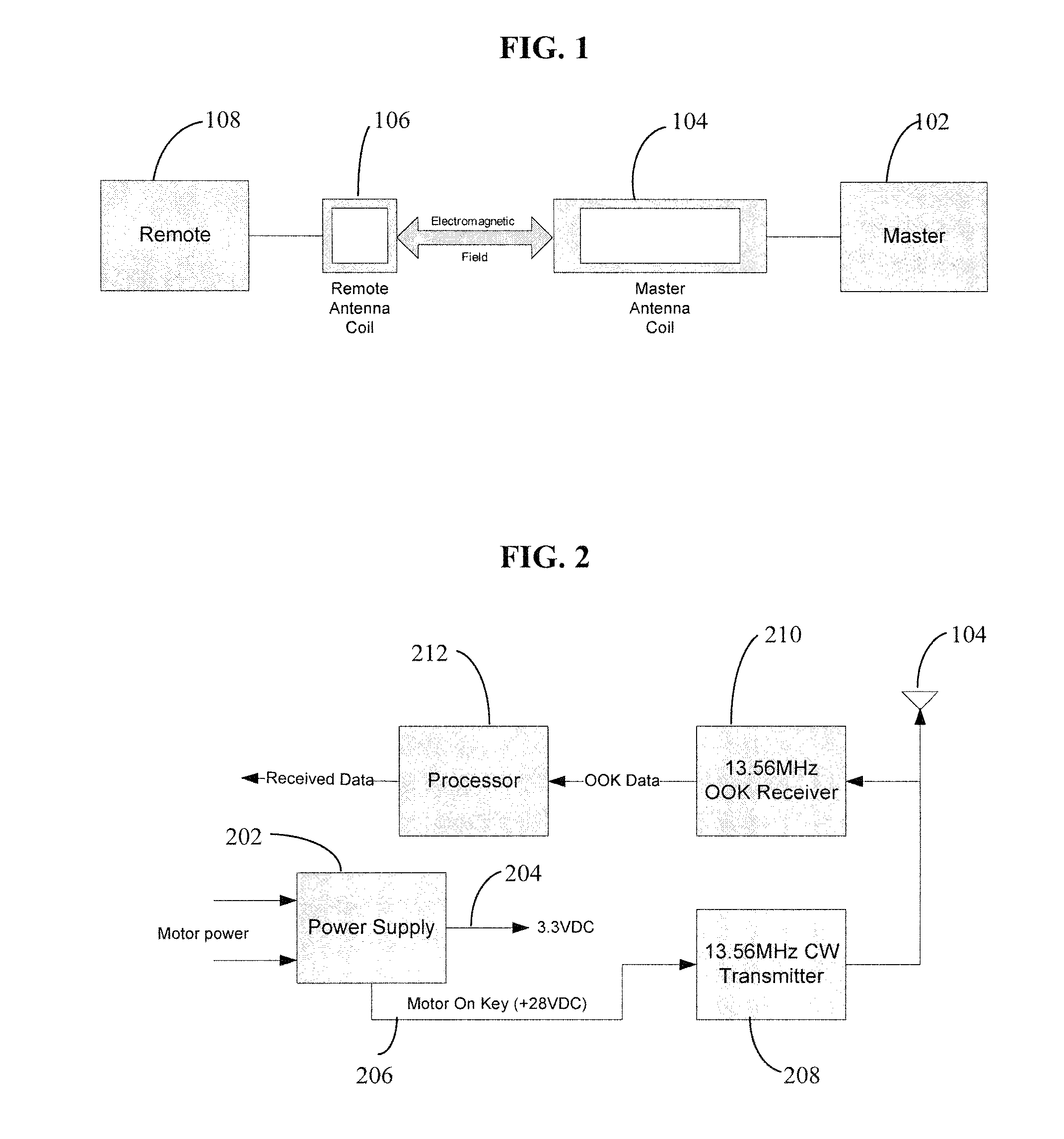
[0016]FIG. 1 is a block diagram of the described embodiment. Master unit 102 is connected to master antenna coil 104, which is electromagnetically coupled to remote antenna coil 106. Remote antenna coil 106 provides power and connectivity for remote unit 108. The amount of power that can be transferred electromagnet...


PUM


Abstract

A wireless system including an antenna, an electrical energy storage unit connected to the antenna, the energy storage unit receiving power via electromagnetic coupling of the antenna with an RF field generated by a master unit, and an electronics package. The electronics package is powered by the energy storage unit, and it includes a sensor, a processor that is capable of acquiring data from the sensor, and a transmitter connected to the processor and to the antenna, wherein the energy storage unit is capable of storing sufficient energy to supply power for the processor to format a message containing data acquired from the sensor and for the transmitter to transmit the message wirelessly via the antenna.

Description

[0001] This application claims the benefit of U.S. Provisional Application No. 60 / 815,965, filed Jun. 23, 2006, which is incorporated herein by reference.TECHNICAL FIELD [0002] This invention relates to wireless transmission of power to a data gathering device equipped with a power receiver, power storage device, and a data transmitter. BACKGROUND OF THE INVENTION [0003] Wireless devices are usually powered by batteries. Since batteries have a finite life, they need to be replaced from time to time. But replacing batteries in wireless devices that are hard to access can be difficult and costly. Furthermore, batteries can fail at inopportune, unpredictable times. In applications where temporary outages of remote devices are not acceptable, batteries must be replaced preventively on a regular basis. The problem is especially troublesome for remote RF receivers because they must be on continuously in order to be able to receive a transmission. When the remote device includes a transmit...

Claims


Application Information

Patent Timeline
Patent Type & Authority Applications(United States)
IPC IPC(8): G08B1/08
CPCH02J17/00G01D21/00H02J50/10H02J50/23H02J50/90H02J50/40H02J50/80H02J50/001
Inventor IVERSON, RODMCKERNAN, EDWARD J.BOOST, MICHAELSEITZ, FORRESTBLAIR, HARVEY
Owner SECURAPLANE TECH
Why Eureka
Try Eureka