Liquid ejecting apparatus and method for controlling liquid ejecting apparatus

a liquid ejecting apparatus and liquid ejecting technology, which is applied in the direction of printing, other printing apparatus, etc., can solve the problems of difficult speeding up recording using minute ink droplets, insufficient ink pressure to dampen the vibration of the meniscus, and significant vibrating of the meniscus, so as to shorten the time between discharge of liquid droplets, quick stabilize, and quick dampen the residual vibration of the liquid in the pressure chamber

Active Publication Date: 2008-02-14
SEIKO EPSON CORP
View PDF5 Cites 18 Cited by
  • Summary
  • Abstract
  • Description
  • Claims
  • Application Information

AI Technical Summary

Benefits of technology

[0013]One advantage of embodiments of the invention is that because the time from the beginning of the first discharging element to the end of the second contracting element is ½ to 1 of the natural vibration period of the liquid in the pressure chamber, the liquid in the pressure chamber after the discharge can be quickly stabilized. Thus, the residual vibration of the liquid in the pressure chamber can be quickly dampened, and the time between discharges of a liquid droplets can be shortened, and the recording time can be improved.
[0014]In another embodiment, the time from the beginning to the end of the second expanding element is set to less than or equal to the period of the natural vibration of the pressure generator. Advantageously, since the time from the beginning to the end of the second expanding element is set to less than or equal to the natural vibration period of the pressure generator, the vibration due to the natural vibration period of the pressure generator can be prevented from affecting the liquid in the pressure chamber.
[0015]In another embodiment, the time from the beginning of the second expanding element to the beginning of the second contracting element is set to less than or equal to the natural vibration period Ta of the pressure generator. Since the time from the beginning of the second expanding element to the beginning of the second contracting element is set to less than or equal to the natural vibration period of the pressure generator, the vibration due to the natural vibration of the pressure generator can be prevented from affecting the liquid in the pressure chamber. Therefore, destabilization of the liquid in the pressure chamber after the discharge of a liquid droplet can be prevented, and the residual vibration of liquid can be easily converged. Thus, the time between discharges of a liquid droplets can be shortened, and the recording time can be improved.

Problems solved by technology

One difficulty in such printers is that the rapid expansion and contraction of the pressure chamber causes the meniscus to vibrate significantly.
Typically, a damping element which expands the pressure chamber so as to reduce the ink pressure is not sufficient to dampen the vibration of the meniscus in the required amount of time.
Thus, when dots (minute ink droplets) are successively discharged from the same nozzle, the time from the discharge of dot 1 to the discharge of dot 2, i.e., must be long enough to stabilize the vibration of the meniscus, as shown in FIG. 7, meaning that it is difficult to speed up recording using minute ink droplets.

Method used


Image

  • Liquid ejecting apparatus and method for controlling liquid ejecting apparatus
  • Liquid ejecting apparatus and method for controlling liquid ejecting apparatus
  • Liquid ejecting apparatus and method for controlling liquid ejecting apparatus

Examples


Embodiment Construction

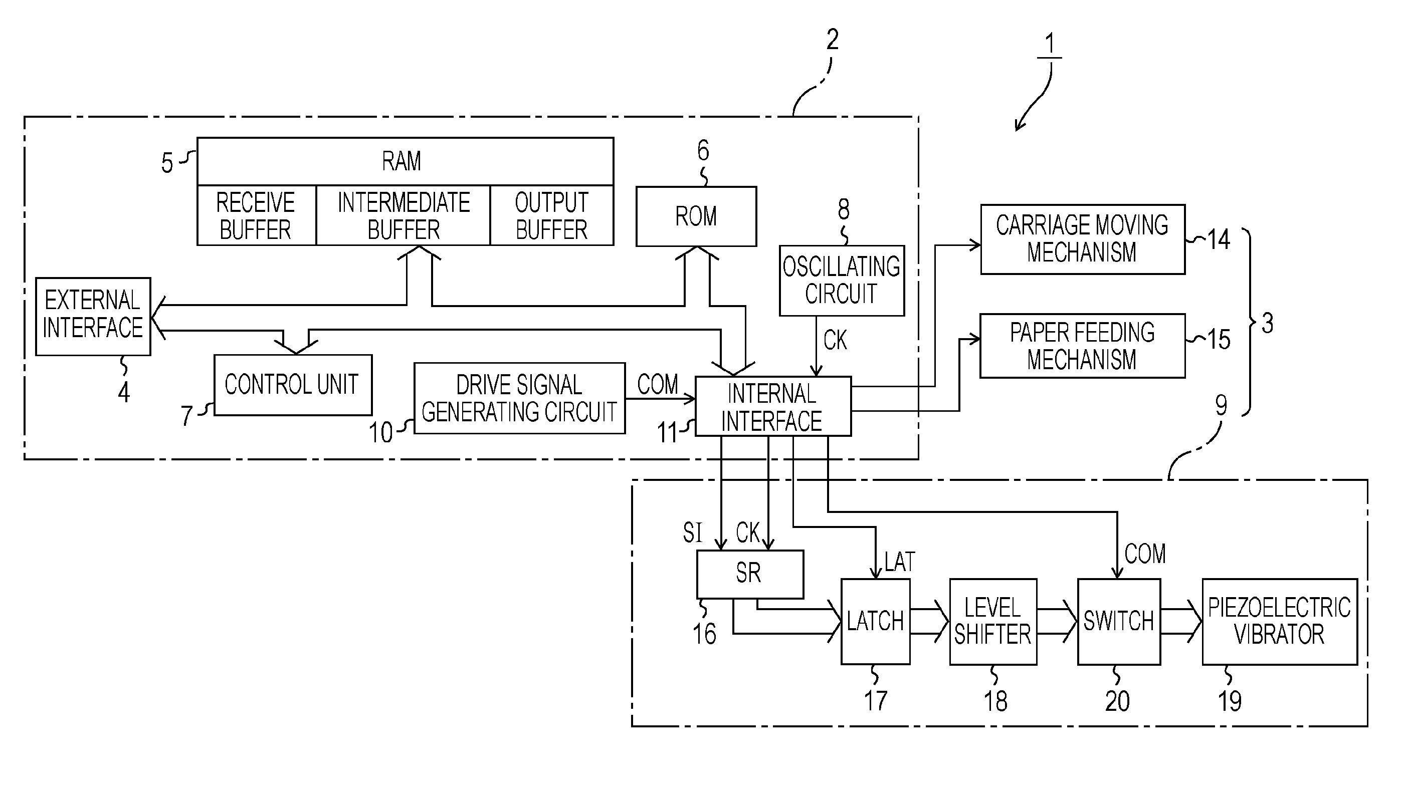
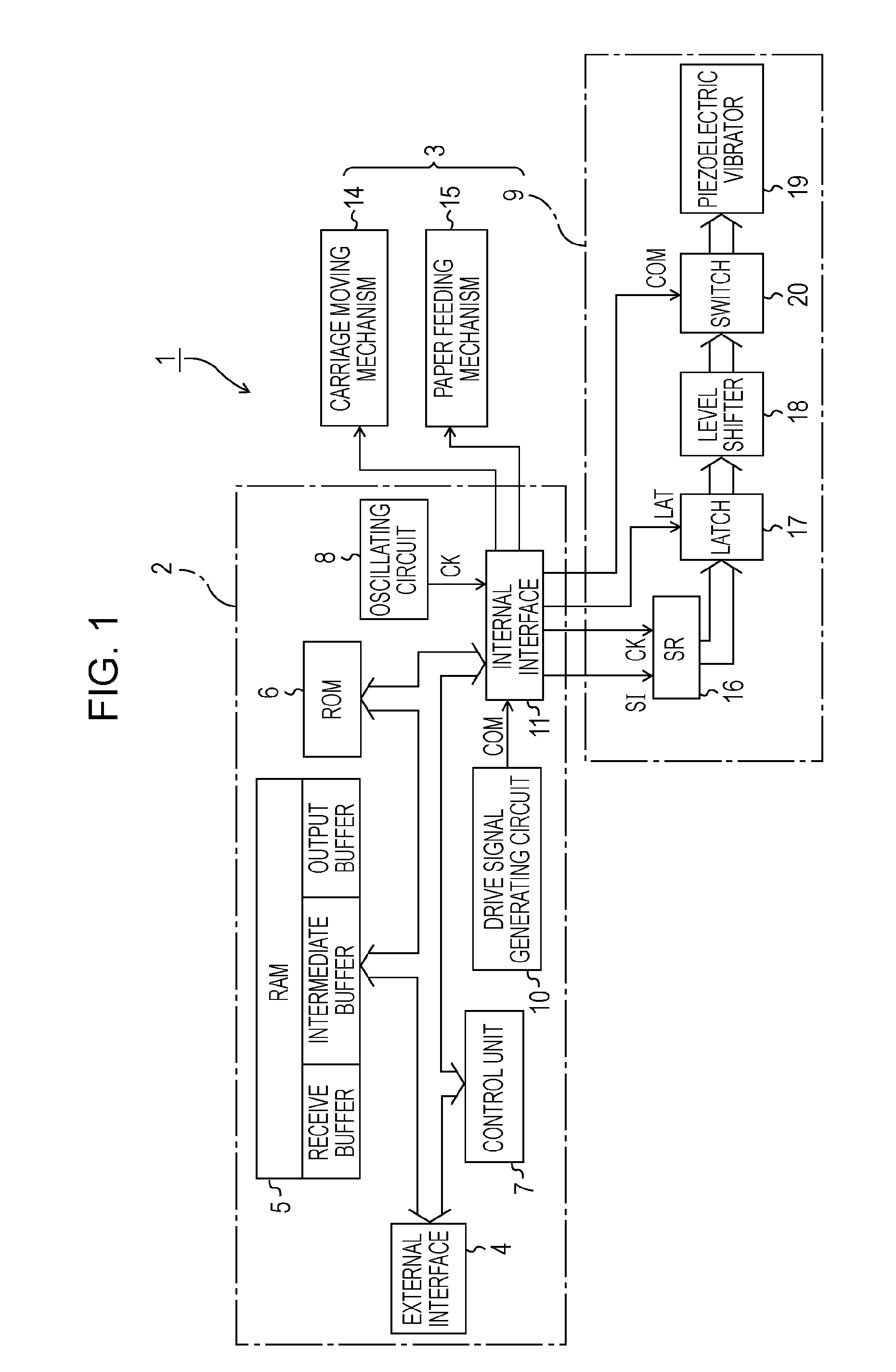
[0024]The exemplary embodiments of the invention will now be described with reference to the drawings. An ink jet printer (hereinafter referred to as printer 1) is used as an example of a liquid ejecting apparatus of the invention. FIG. 1 is a functional block diagram of the printer 1.

[0025]As shown in FIG. 1, the printer 1 includes a printer controller 2 and a print engine 3. The printer controller 2 includes an external interface 4, a RAM 5, a ROM 6, a control unit 7, an oscillating circuit 8, a drive signal generating circuit 10, and an internal interface 11. Print data from an external device, such as a host computer (not shown), is inputted into the external interface 4. The RAM 5 stores various data. The ROM 6 stores a control routine for processing various data. The control unit 7 includes a CPU. The drive signal generating circuit 10, corresponds to a drive signal generator, and generates a drive signal that is supplied to a recording head 9. The internal interface 11 output...


PUM


Abstract

A liquid ejecting apparatus includes a liquid ejecting head with a pressure chamber communicating with a nozzle opening and a pressure generator capable of causing a pressure fluctuation to liquid in the pressure chamber. The liquid ejecting head discharges liquid droplets by operating the pressure generator. The drive signal generator generates a drive signal including a drive pulse which includes a first expanding element that expands the pressure chamber, a first discharging element that contracts the pressure chamber expanded by the first expanding element in order to discharge a liquid droplet, a second expanding element that expands the pressure chamber, and a second contracting element that contracts the pressure chamber. The time from the beginning of the first discharging element to the end of the second contracting element is set to ½ to 1 of the natural vibration period of the liquid in the pressure chamber.

Description

BACKGROUND[0001]The entire disclosure of Japanese Patent Application No. 2006-216430, filed Aug. 9, 2006 is expressly incorporated herein by reference.[0002]1. Technical Field[0003]The present invention relates to a liquid ejecting apparatuses. More specifically, the present invention relates to liquid ejecting apparatuses capable of controlling the discharge of liquid droplets from each nozzle opening by controlling the supply of a drive pulse to a pressure generator.[0004]2. Related Art[0005]A liquid ejecting apparatus typically has a liquid ejecting head which is capable of discharging various liquids from the liquid ejecting head in the form of droplets. Examples of common liquid ejecting apparatuses are image recording apparatuses such as ink jet printers, which perform a recording process by discharging (ejecting) liquid ink onto recording paper in a series of dots. In recent years, liquid ejecting apparatuses have been used not only in image recording apparatuses but also in ...

Claims


Application Information

Patent Timeline
Patent Type & Authority Applications(United States)
IPC IPC(8): B41J29/38
CPCB41J2/04581B41J2/04588B41J2/14274B41J2/04591B41J2/04598B41J2/0459
Inventor IHARA, SEIJI
Owner SEIKO EPSON CORP
Why Eureka
Try Eureka