Hinge assembly for display

a technology for assembling and displaying parts, which is applied in the direction of wing accessories, electric apparatus casings/cabinets/drawers, instruments, etc., can solve the problems of high material cost, low yield rate, and large quantity of required elements, so as to simplify the structure, reduce the cost of materials, and facilitate the manufacturing process

Inactive Publication Date: 2008-02-14
LITE ON TECH CORP
View PDF3 Cites 3 Cited by
  • Summary
  • Abstract
  • Description
  • Claims
  • Application Information

AI Technical Summary

Benefits of technology

[0009]One particular aspect of the present invention is to provide a hinge assembly to lower the cost of material and simplify the structure. The manufacturing process becomes easily, the assembling tolerance is lowered, the yield rate is enhanced, and its structural strength is unchanged. It also has a good performance.

Problems solved by technology

The structure is complex, the quantity of required elements is large, and the cost of the materials is high.
Besides, the assembling tolerance is large, and the yield rate is low.
The structure of the mentioned prior art also involves in the problems of complex design, high material cost, large assembling tolerance and low yield rate.

Method used


Image

  • Hinge assembly for display
  • Hinge assembly for display
  • Hinge assembly for display

Examples


Embodiment Construction

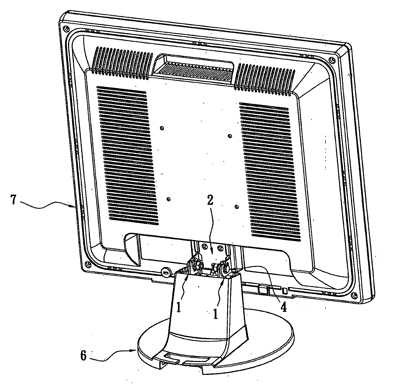
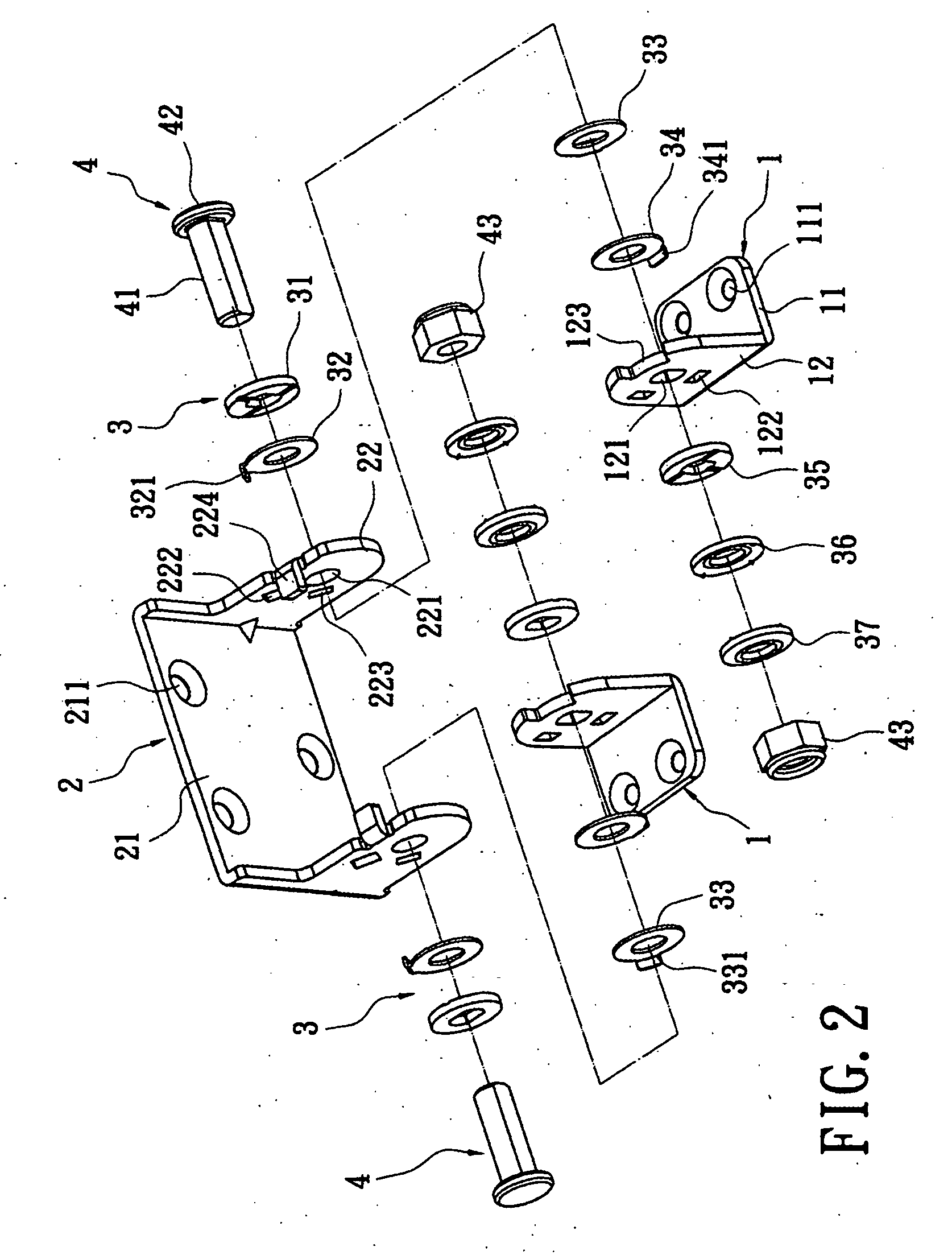
[0021]Reference is made to FIGS. 2-6. The hinge assembly includes two connecting bases 1, a rotating element 2, two sets of washers 3, and two locking elements 4. The two connecting bases 1 are made of metal boards. Each of the connecting bases 1 includes a base part 11 and a first ear part 12 vertically extending from one side of the base part 11, such as a board in form of L-shaped or LL-shaped (i.e. two parallel ear parts). On the base part 11, there are two connecting holes 111. The base part 11 is screwed on the base 6 of an LCD (as shown in FIG. 7) by the screws. The first ear part 12 has a non-circular first shaft hole 121. At outside area of the first shaft hole 121, there is a second through hole 122. At an edge of the first ear part 12, there is a concave opening 123. The concave opening 123 formed a similar U-shape establishes an opening angle with a specific angle. Preferably, 5 degreed forwards to 30 degreed backwards for the best mode of the present invention. Specific...


PUM


Abstract

A hinge assembly includes two connecting bases, a rotating element, two sets of washers, and two locking elements. The connecting base includes a base part and a first ear part. The first ear part has a first shaft hole and a concave opening. The rotating element includes a linking part and two second ear parts. The second ear part has a second shaft hole and a blocking protrusion. The rotating element straddles and is located on two connecting bases. The two blocking protrusions respectively place into two concave openings. The two sets of washers are located on a side of the first ear parts and the two second ear parts. The locking elements insert within the first shaft holes of the two connecting bases, the second shaft holes of the rotating element, and the two sets of washers. Thereby, the two connecting bases are pivoted with the rotating element.

Description

BACKGROUND OF THE INVENTION[0001]1. Field of the Invention[0002]The present invention relates to a hinge assembly. In particular, it is applied to the display device of each electronic apparatus, such as an LCD, and is used for supporting and adjusting the angle of the display panel.[0003]2. Description of the Related Art[0004]Because LCDs are thin, light, and small, and consume a small amount of power, LCDs are widely applied to information apparatus. In order to allow a user to view the display at the best possible viewing angle, there is a hinge assembly between the display panel and the base of the LCD. The hinge assembly can support the LCD and allows the viewing angle to be adjusted.[0005]FIG. 1 shows a hinge assembly of the prior art. The hinge assembly 9 includes a connecting base 91, a bottom board 92, a rotating element 93, and two locking elements 94. The connecting base 91 is a U-shaped board. The bottom of the connecting base 91 is connected with the bottom board 92 via...

Claims


Application Information

Patent Timeline
Patent Type & Authority Applications(United States)
IPC IPC(8): H05K7/16
CPCE05D11/087E05Y2900/606F16M2200/08F16M2200/024F16M11/10
Inventor HUANG, CHIEN-CHENG
Owner LITE ON TECH CORP
Why Eureka
Try Eureka