
Working mechanical device and manipulator

a mechanical device and manipulator technology, applied in gearing, medical science, surgery, etc., can solve the problems of limited relative layout of the opening/closing axis and the attitude axis of the gripper

Active Publication Date: 2008-02-14
KARL STORZ GMBH & CO KG
View PDF2 Cites 69 Cited by
  • Summary
  • Abstract
  • Description
  • Claims
  • Application Information

AI Technical Summary

Benefits of technology

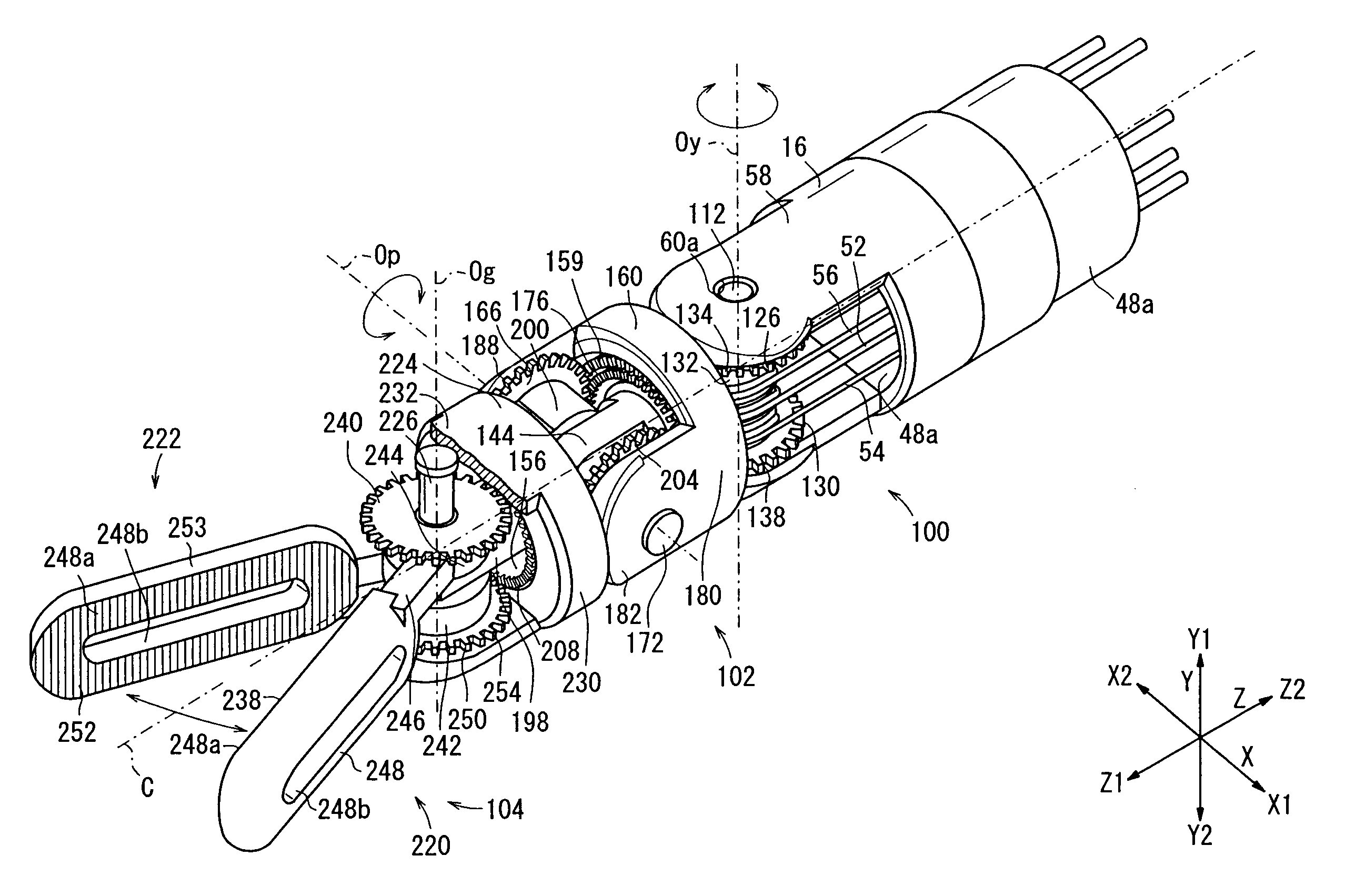
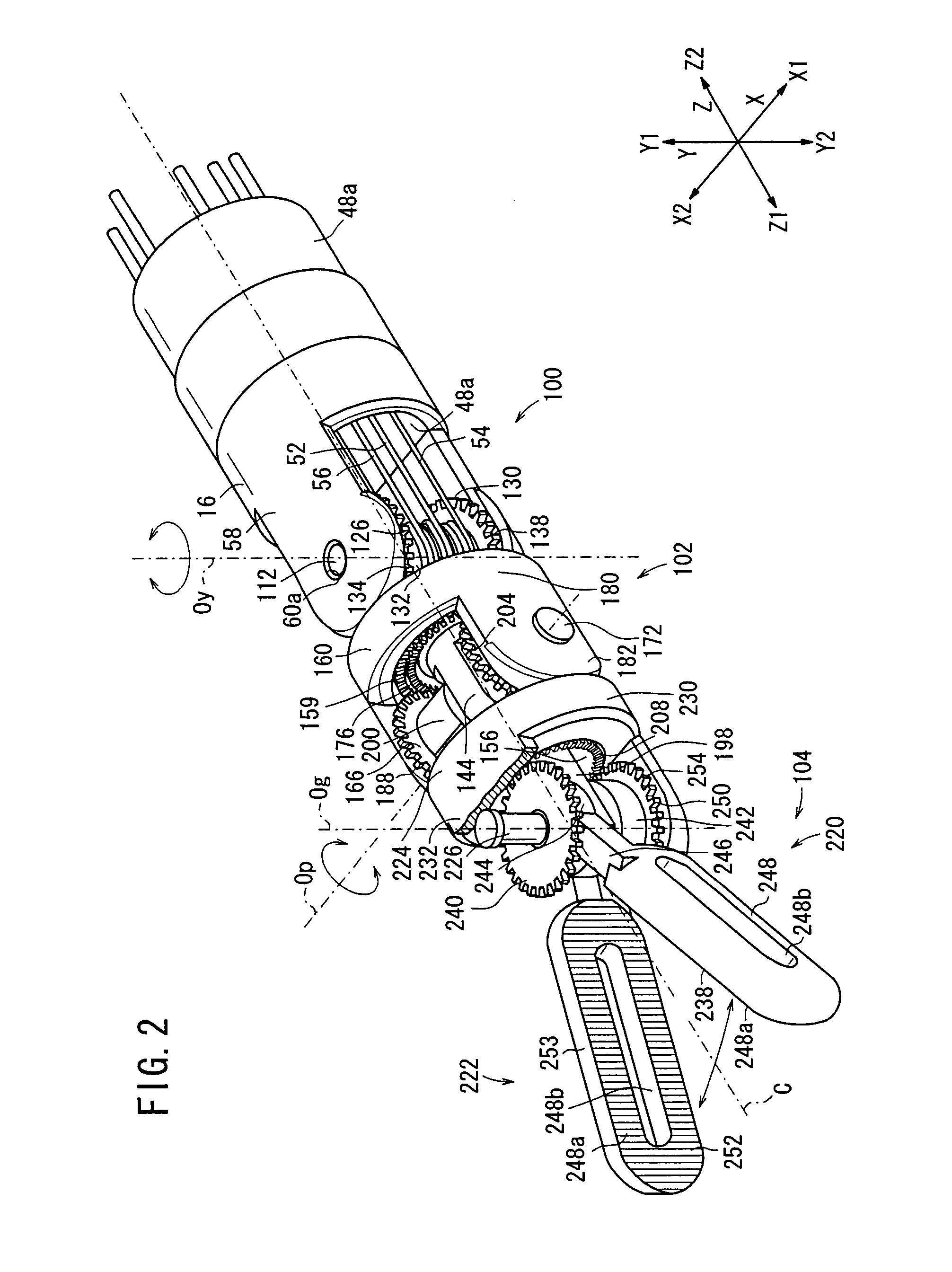
[0010]A working mechanical device according to the present invention comprises a first drive rotor rotatable in a direction perpendicular to a reference axis, a first intermediary rotor including an axial proximal end surface held in contact with the first drive rotor, and rotatable about the reference axis to change the direction of rotation of the first drive rotor, a first end effector drive member held in contact with an axially distal end surface of the first intermediary rotor at one side of the center thereof, and rotatable about an opening and closing axis perpendicular to the reference axis to change the direction of rotation of the first intermediary rotor, and a second end effector drive member held in contact with an axially distal end surface of the first intermediary rotor at an opposite side of the center thereof, and rotatable in a direction opposite to the direction in which the first end effector drive member rotates, about the opening and closing axis perpendicular to the reference axis to change the direction of rotation of the first intermediary rotor.
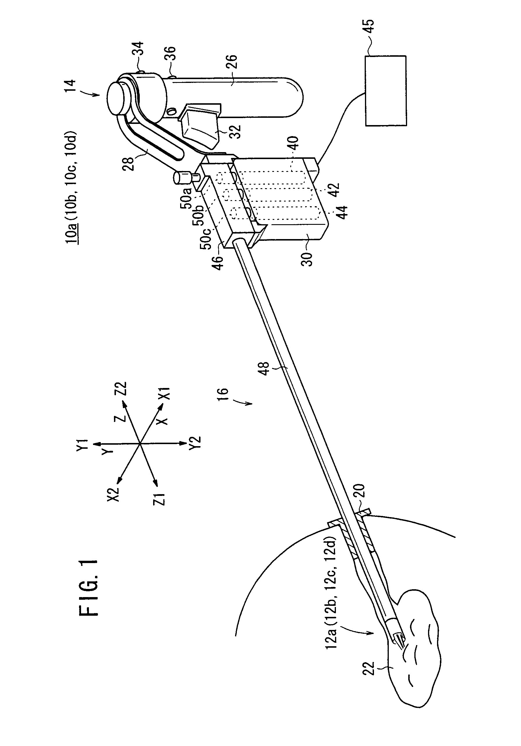
[0011]A manipulator according to the present invention comprises the above-mentioned working mechanical device, an operation unit held by hand, an input member mounted on the operation unit and operable by hand, a rotational source rotatable based on operation of the input member, and a flexible power transmitting member.

Problems solved by technology

Consequently, the opening / closing axis and the attitude axis of the grippers are limited in their relative layout.

Method used


Image

  • Working mechanical device and manipulator
  • Working mechanical device and manipulator
  • Working mechanical device and manipulator

Examples


second embodiment

[0106]A manipulator 10b according to the present invention will be described below with reference to FIGS. 14 and 15. The manipulator 10b has an operation command unit 14 and a connector 16 which are identical to the operation command unit 14 and the connector 16 of the manipulator 10a, and includes a working unit 12b instead of the working unit 12a.

first embodiment

[0107]As shown in FIGS. 14 and 15, the working unit 12b incorporates therein mechanisms of three degrees of freedom. These mechanisms include a mechanism having a first degree of freedom for angularly moving a portion of the working unit 12b that is positioned ahead of a first rotational axis Oy extending along the Y directions, in yawing directions about the first rotational axis Oy, a mechanism having a second degree of freedom for angularly moving the portion of the working unit 12b in rolling directions about a second rotational axis Or extending along the Z directions, and a mechanism having a third degree of freedom for opening and closing an end effector 104 on the distal end of the working unit 12b about a third rotational axis Og symmetrically with respect to a reference axis C. The second rotational axis Or is held in alignment with the reference axis C. The working unit 12b comprises a wire-driven mechanism 400, a drive mechanism 402, and the end effector 104. The end eff...

third embodiment

[0115]A manipulator 10c according to the present invention will be described below with reference to FIGS. 16 through 19. The manipulator 10c has an operation command unit 14 and a connector 16 which are identical to the operation command unit 14 and the connector 16 of the manipulator 10a, and includes a working unit 12c instead of the working unit 12a.

[0116]As shown in FIGS. 16 and 17, like the working unit 12a, the working unit 12c comprises mechanisms of three degrees of freedom for turning an end effector in yawing and pitching directions and opening and closing grippers. The gripper is opened and closed by a link mechanism. The working unit 12c comprises a wire-driven mechanism 100, a drive mechanism 502, and an end effector 504. The wire-driven mechanism 100 is identical to the above wire-driven mechanism 100 according to the first and second embodiments.

[0117]The drive mechanism 502 differs from the drive mechanism 102 in that it includes an end effector main shaft 506 in p...


PUM


Abstract

A working unit comprises a gear body rotatable in a direction perpendicular to a reference axis, a gear ring including a proximal end surface held in contact with the gear body and rotatable about the reference axis to change the direction of rotation of the gear body, a first end effector body held in contact with an axially distal end surface of the gear ring at an upper portion thereof, and rotatable about a rotational axis perpendicular to the reference axis to change the direction of rotation of the gear ring, and a second end effector body held in contact with the axially distal end surface of the gear ring at a lower portion thereof, and rotatable in a direction opposite to the direction in which the first end effector body rotates, about the rotational axis. The first end effector body and the second end effector body are openable and closable symmetrically with respect to the reference axis.

Description

BACKGROUND OF THE INVENTION[0001]1. Field of the Invention[0002]The present invention relates to a working mechanical device for opening and closing a pair of end effector bodies with a power transmitting mechanism for performing certain treatments on a living body tissue, and a manipulator having such a working mechanical device on its distal end for performing manipulating actions from the other end thereof through an arm or the like.[0003]2. Description of the Related Art[0004]According to laparoscopic surgery, it is customary to form a plurality of holes in the abdominal part of the patient, insert an endoscope and a manipulator (or forceps) into the respective holes, and perform the surgical operation while images captured by the endoscope are being observed on a display monitor by the surgeon. Since such a laparoscopic surgical operation does not require the abdominal cavity to be opened, the burden on the patient is small and the number of days which the patient needs to reco...

Claims


Application Information

Patent Timeline
Patent Type & Authority Applications(United States)
IPC IPC(8): F16H7/02A61B34/30A61B90/00
CPCA61B19/22A61B2017/2936A61B2019/2249A61B2019/2242A61B2017/2939A61B34/70A61B34/71A61B34/72
Inventor JINNO, MAKOTOSUNAOSHI, TAKAMITSUOMORI, SHIGERU
Owner KARL STORZ GMBH & CO KG
Learn More