Distal targeting device

Active Publication Date: 2008-02-14
STRYKER EURO OPERATIONS HLDG LLC
View PDF30 Cites 81 Cited by
  • Summary
  • Abstract
  • Description
  • Claims
  • Application Information

AI Technical Summary

Benefits of technology

[0010]The present invention is intended to make locating the screws easier and more accurate. An aiming or targeting arm is attached to a known nail-holding arm. In a preferred embodiment a fixation bolt is used to hold a targeting apparatus including the aiming arm in a bore of the nail-holding arm. A clamping device with a hand locking mechanism may also be used to hold the targeting apparatus in the nail holdi

Problems solved by technology

This locking is complicated by the deflection of the nail during insertion into the bone canal which changes the location of the cross bore from their static position.
A common problem in such a procedure is that the instruments are “in the way” since they are on the image plane of the C-arm.
Furthermore, distal locking is pro

Method used


Image

  • Distal targeting device
  • Distal targeting device
  • Distal targeting device

Examples


Embodiment Construction

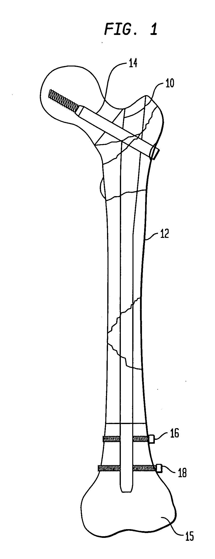
[0067]Referring to FIG. 1, there is shown a typical intramedullary nail 10 used for fracture fixation such as sold by Stryker Trauma GmbH as a GA® long bone nail. Nail 10, when used in a femur 12 includes a lag screw 14 for insertion into the head of a femur and a pair of distal locking screws 17 going through bore 16 and oblong hole 18, which engage the cortical bone on both the lateral and medial sides of the distal femur 15.

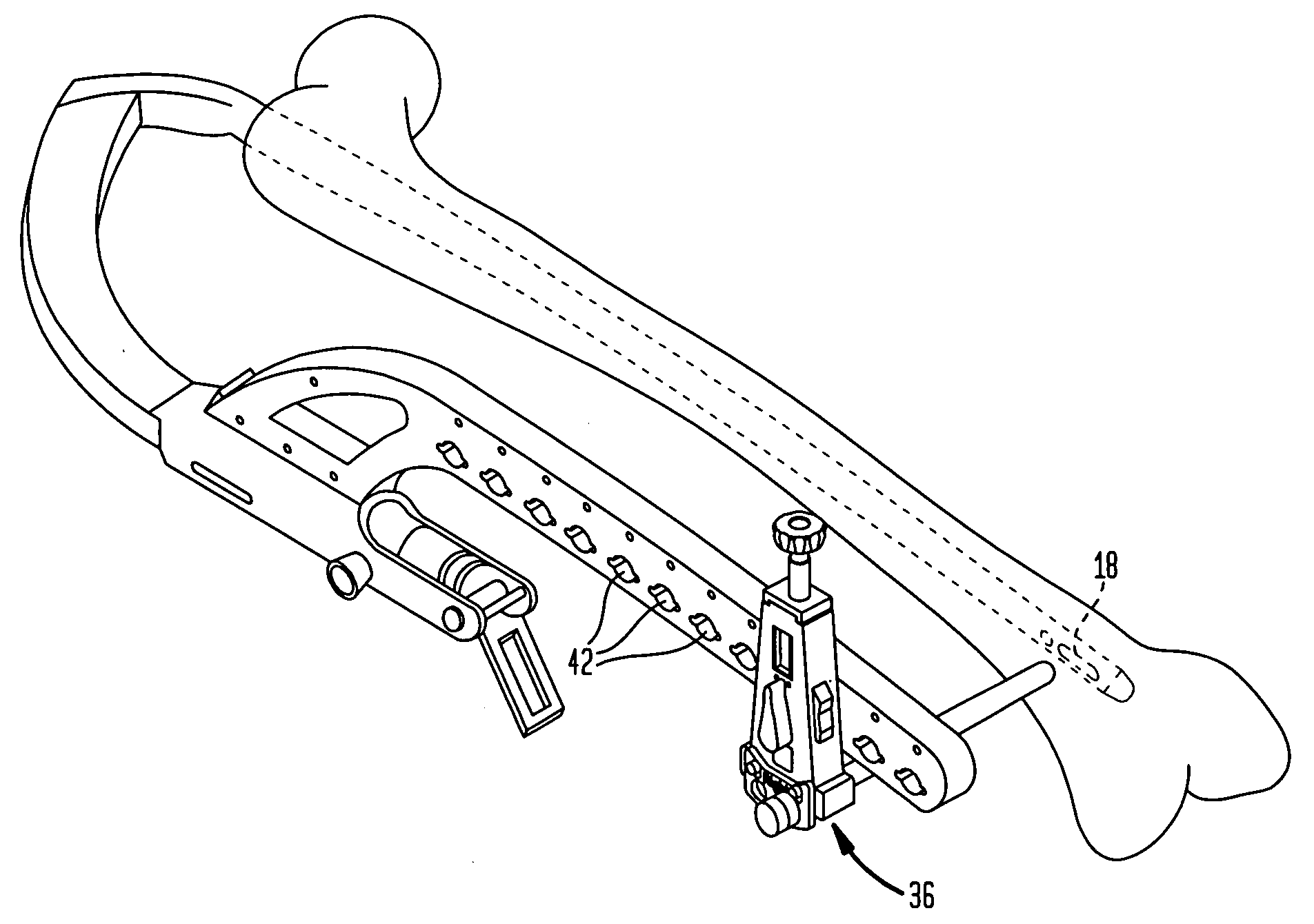
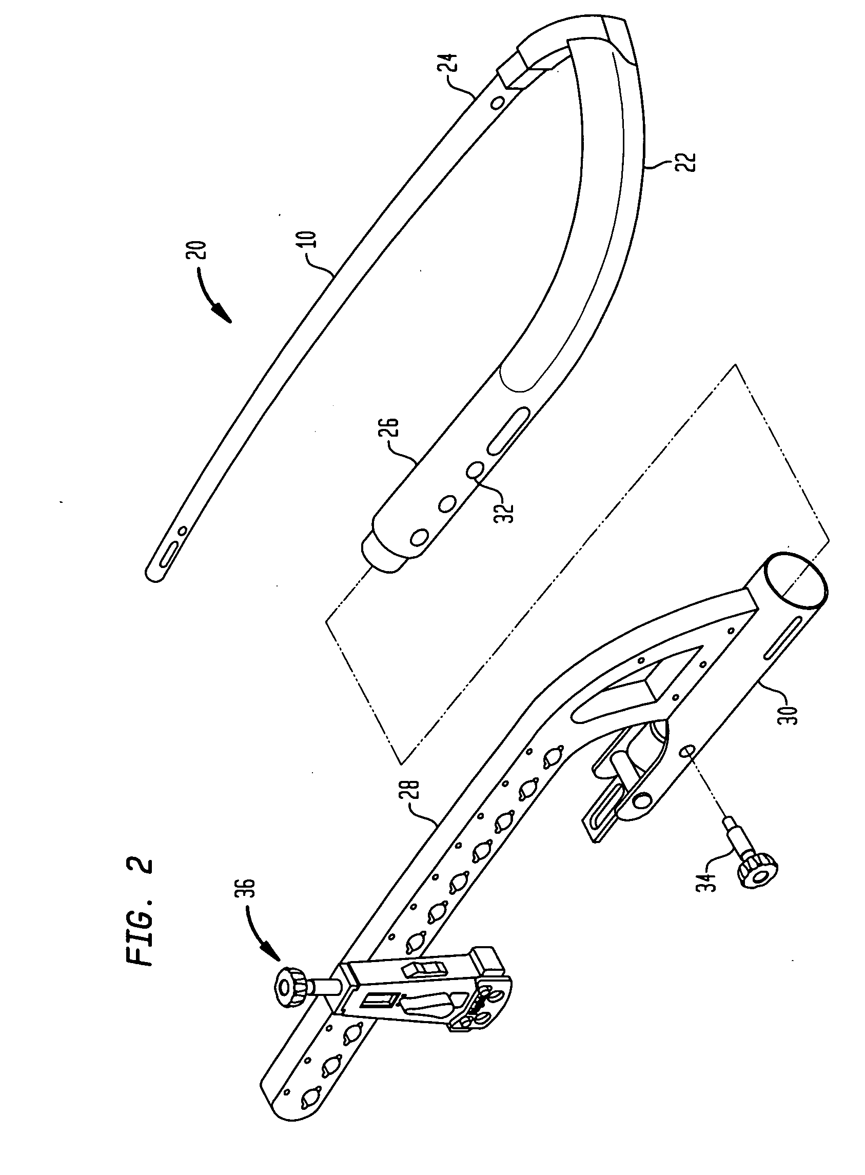
[0068]Referring to FIG. 2, there is shown a partially assembled targeting apparatus of the present invention generally denoted as 20, which includes a handle portion 22 coupled to proximal end 24 of femoral intramedullary nail 10. Handle 22 may be coupled by a threaded connection to proximal end 24 of nail 10 or in any other manner all of which are well-known in the art. In a preferred embodiment, handle 22 includes a coupling portion 26, which is adapted to receive various targeting apparatus for locating and drilling the bone for receipt of the femoral lag s...


PUM


Abstract

A targeting device for targeting a cross bore in a bone nail has an arm member coupled to an end portion of the bone nail and an aiming portion forming part of the arm member extending parallel to a longitudinal axis of the bone nail. An adjustable aiming device is mounted on the aiming portion, the adjustable device having a guide bore alignable with the cross bore in the nail. The adjustable device is moveable with respect to the aiming portion in a direction perpendicular to a plane containing both the nail longitudinal axis and central axis of the cross bore. A target indicator is mounted on the adjustable aiming device. The target indicator has a radiolucent body including first and second spaced parallel planar portions each having a spaced radiopaque element therein.

Description

CROSS-REFERENCE TO RELATED APPLICATIONS[0001]This application claims the benefit of the filing date of U.S. Provisional Patent Application No. 60 / 836,793 filed Aug. 10, 2006, the disclosure of which is hereby incorporated herein by reference.BACKGROUND OF THE INVENTION[0002]In order to accurately lock long intramedullary nails (i.e. those with distal attachment screws) the distal screws have to be accurately aligned with the cross bores in the nail. This locking is complicated by the deflection of the nail during insertion into the bone canal which changes the location of the cross bore from their static position. Typically the surgeon has been forced to do this freehand with the help of an x-ray C-arm. A common problem in such a procedure is that the instruments are “in the way” since they are on the image plane of the C-arm. Furthermore, distal locking is problematic since the distal bores cannot be made precisely through the soft tissue due to the anatomical shape of the femur an...

Claims


Application Information

Patent Timeline
IPC IPC(8): A61B17/60
CPCA61B17/1703A61B17/72A61B17/1725
Inventor GIERSCH, HELGEDORAWA, KLAUSSIMON, BERNDVOLZOW, STEFAN
Owner STRYKER EURO OPERATIONS HLDG LLC
Why Eureka
Try Eureka