
Blade holder having displacement-dependent spring force compensation

Active Publication Date: 2008-02-21
DIENES WERKE FUER MASCHTEILE
View PDF6 Cites 1 Cited by
  • Summary
  • Abstract
  • Description
  • Claims
  • Application Information

AI Technical Summary

Benefits of technology

"The invention is about an adjustment mechanism for a piston that can compensate for changes in the spring force as the piston moves closer to its maximum position. The piston surface is designed to increase as it moves, so that the air pressure acting on it also increases. This results in a higher piston force at the end of the adjustment path, while the air pressure remains the same. The piston surface can be increased in a continuous or stepwise manner, and the adjustment piston can be provided with extensions or multiple extensions of different sizes to achieve the desired force. The invention allows for a more uniform cutting force at different positions in the piston."

Problems solved by technology

Since over the adjustment path of the adjustment mechanism, depending upon the position of the blade holder on the cutting machine, different cutting positions with the circular blade resting upon the lower blade can result, the known construction of a blade holder has the drawback that at respectively the same air driving pressure, in different cutting positions different cutting forces are also established, because a respective spring force of the biasing compression spring, which spring force varies in magnitude as a function of the spring characteristics or of spring tolerances, counteracts the air driving pressure in the various cutting positions.

Method used


Image

  • Blade holder having displacement-dependent spring force compensation
  • Blade holder having displacement-dependent spring force compensation
  • Blade holder having displacement-dependent spring force compensation

Examples


Embodiment Construction

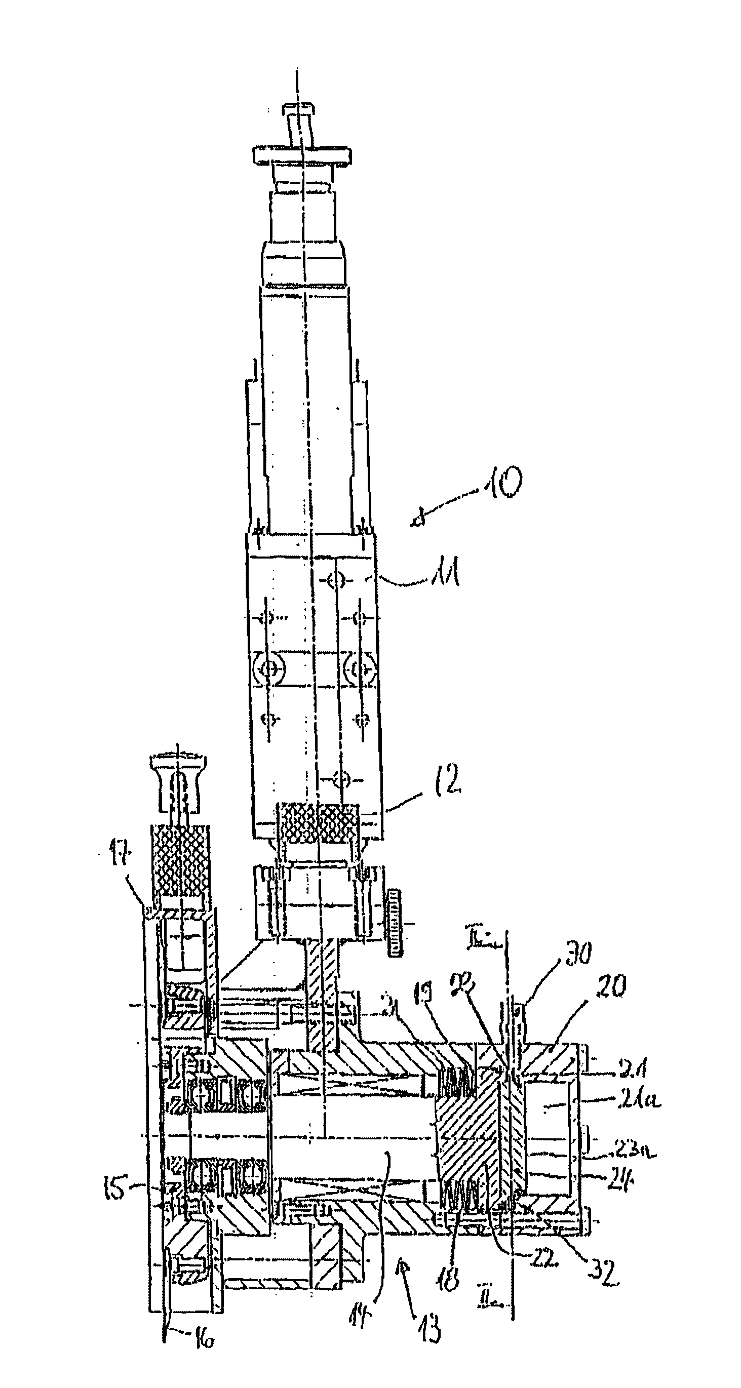
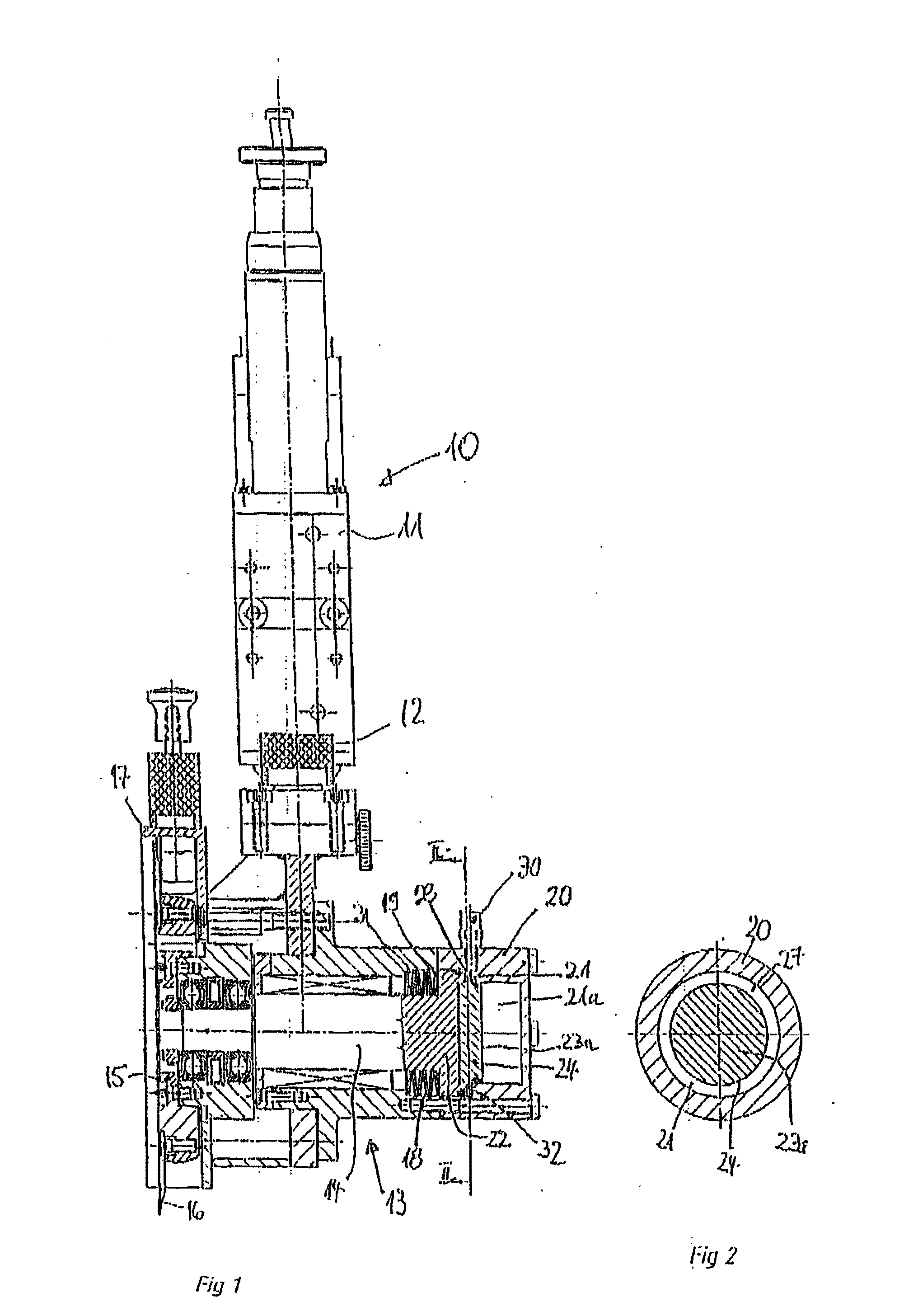
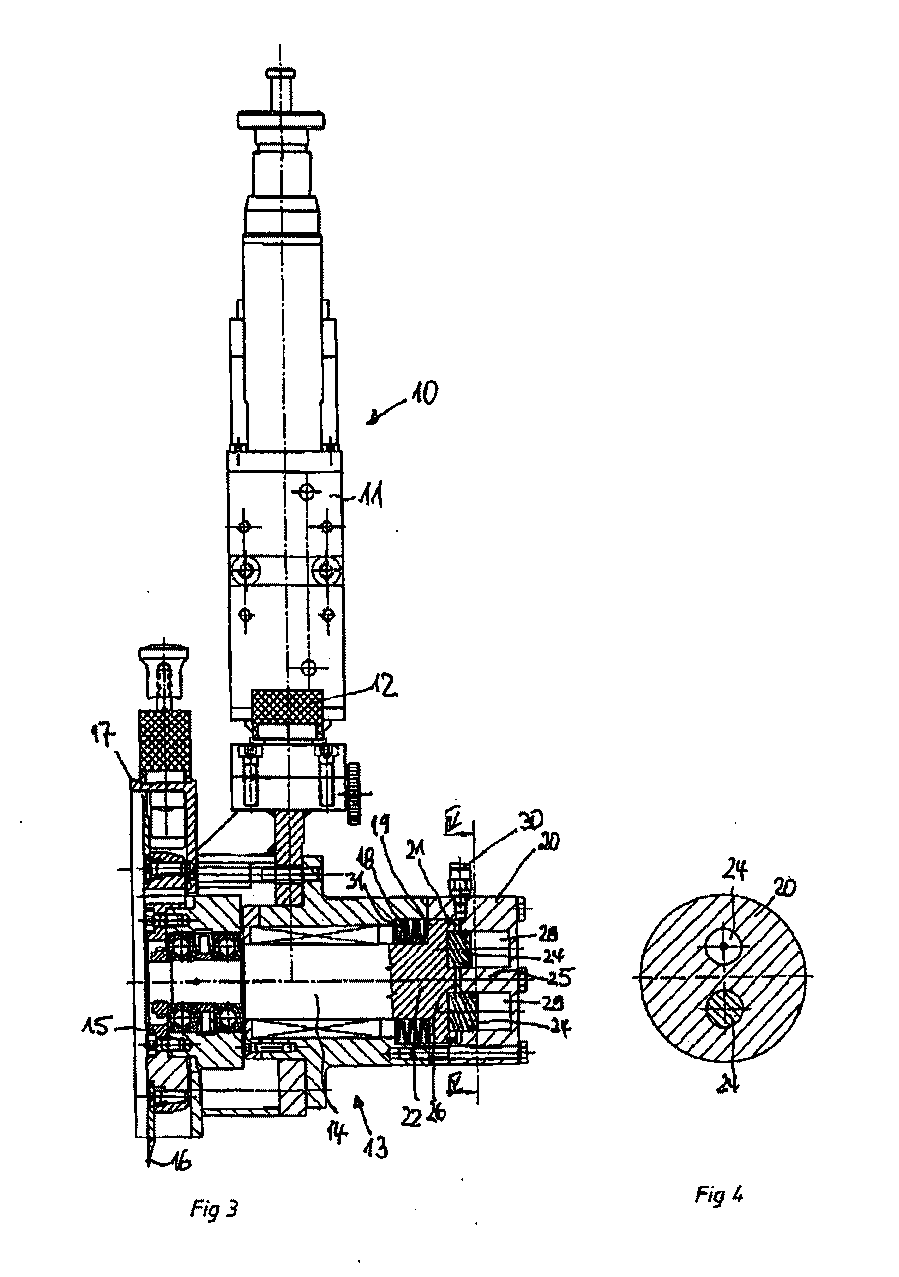
[0022] With the blade holder 10 shown in FIG. 1, disposed at the end of a lowering piston rod 12 having a raising and lowering device 11, which is not part of the subject matter of this invention and furthermore belongs to the state of the art pursuant to DE 38 41 576 C1, is a cutter or blade head 13 in which an adjustment piston rod 14 is displaceably disposed transverse to the axis of the lowering piston rod 12. Mounted on the associated end of the adjustment piston rod 14 is a blade carrier 15 on which is held a circular blade 16. In the ready position of the circular blade 16 illustrated in the drawing, the circular blade is surrounded by a hand guard 17.

[0023] As not further illustrated, by shifting the adjustment piston rod 14 to the left in the illustrated drawing, the circular blade 16 can be brought into a non-illustrated cutting position in which it cooperates with a similarly not-illustrated lower blade.

[0024] To carry out this adjustment movement, disposed in the blade...


PUM

PropertyMeasurementUnit
cutting forceaaaaaaaaaa
areaaaaaaaaaaa
spring forceaaaaaaaaaa

Abstract

A blade holder for cutting machines includes a blade head held on a raising and lowering device and having an adjustment mechanism for a circular blade that is held on the blade head. The adjustment mechanism for the movement of the circular blade between a cutting position and a ready position, is provided with an adjustment piston rod having an adjustment piston that is guided in a chamber of the blade head housing and can is adapted to be moved by compressed air. The adjustment piston rod is biased by a compression spring into the ready position of the circular blade. The piston surface of the adjustment piston has a cross-sectional area that is configured such that as the path of the adjustment piston in the direction of adjustment increases, the piston surface that is acted upon by compressed air increases.

Description

CROSS-REFERENCE TO A RELATED APPLICATION [0001] This application is a divisional application of U.S. patent application Ser. No 10 / 741,163 filed Dec. 18, 2003. The instant application should be granted the priority dates of Dec. 19, 2002 the filing date of the corresponding German patent application 102 60 031.7.BACKGROUND OF THE INVENTION [0002] The invention relates to a blade holder for cutting machines, with a blade head held on a raising and lowering device, and with an adjustment mechanism for a circular blade that is held on the blade head, whereby for the movement of the circular blade between a cutting position and a ready position, the adjustment mechanism is provided with an adjustment piston rod having a compressed air activated adjustment piston that is guided in a chamber of the blade head housing, and the adjustment piston rod is biased via a compression spring into the ready position of the circular blade. [0003] A blade holder having the aforementioned features is d...

Claims


Application Information

Patent Timeline
Patent Type & Authority Applications(United States)
IPC IPC(8): B26B1/00B26D5/04
CPCB26D5/04Y10T83/7838Y10T83/7847
Inventor SUPE-DIENES, RUDOLFOBERHOFF, FALK
Owner DIENES WERKE FUER MASCHTEILE
Learn More