Further, such systems typically require use of two hands to
mount the device on the weapon, with both hands performing a function beyond merely gripping the weapon.
Moreover, attachment and detachment of these devices can be
time consuming and, in law
enforcement and military applications, such time may be critical to the safety of the weapon's operator or others.
As a result of these and other problems with conventional devices, the user typically leaves the auxiliary device mounted on the weapon or performs a
time consuming operation to
mount the device when needed.
These alternatives are undesirable.
Also, in the context of handweapons, for example, many holsters do not readily accommodate weapons having auxiliary devices mounted thereon.
Thus, it is often difficult to holster or carry a weapon having such a device attached to it.
This presents special problems for law
enforcement officers and others.
Additionally, the user may not want to use the device during
daylight hours, but may want to attach the device to a weapon at night.
Moreover, depending on the configuration of the auxiliary device, the user may need to replace its batteries.
Another problem with conventional auxiliary devices is that the device is often wider than the weapon, or the device protrudes beyond the from end of the weapon.
These characteristics often result in subjecting the auxiliary device to greater
wear and tear because the auxiliary device often contacts various obstructions in the environment where the weapon is being used.
For instance, a device extending beyond the end of a
barrel of a weapon may collide with doorways, clothing, tree branches, or other objects, tending to tear the device apart from the weapon and possibly damaging, or rendering inoperable, the device or the weapon itself.
Another problem is that an assailant may more easily disarm a user by grabbing an auxiliary device which extends substantially beyond the weapon.
The danger of these and other problems occurring are greater at night or when ordinary vision is impaired.
Additionally, many prior auxiliary devices, especially illuminators, are bulky.
This characteristic also is undesirable.
While the '967 Patent overcomes some of the problems traditionally associated with the attachment of an auxiliary device to a weapon, it too leaves room for improvement.
This flexible attachment is not ideal in some circumstances, for example, for use with auxiliary devices requiring precise boresight alignment.
Also, the attachment mechanism is relatively bulky, causing the auxiliary device to be relatively wider, resulting in an increase in the size of the device in at least one dimension.
Moreover, the engagement of portions of the auxiliary device with the corresponding portions of the weapon is limited by the degree of flexibility of the flexible mechanism.
Furthermore, the spring-loaded mechanism also limits the biasing force holding the auxiliary device to a weapon.
As a result, this attachment approach may be successful on weapons, such as handweapons, which have relatively modest
recoil forces, but may be somewhat less successful on other weapons, such as shotguns, where the greater
recoil forces may cause the auxiliary device to dislodge from the weapon.
While lights and other devices primarily have been mounted to weapons, many weapons are not specifically designed to facilitate this.
As a result, special brackets and other mounting devices often need to be used.
Some weapons have mounting racks, but various drawbacks exist even with these types of devices.
In many cases, it is difficult to
mount a device to the weapon and / or complex mechanical structures are necessary.
This difference in dimension may cause an auxiliary device not to fit on to the weapon because the back end of the auxiliary device contacts that front surface of the trigger guard before a spring-biased mechanism can engage in the transverse slot.
Alternatively, the difference in dimension may cause the auxiliary device to unnecessarily extend past the end of the weapon.
This requires the owner to store a second part and adds to the manufactured cost.
This can cause an auxiliary device to fit nicely on some weapons and either be too tight or too loose on another weapon.
Other problems and drawbacks with prior approaches exist.


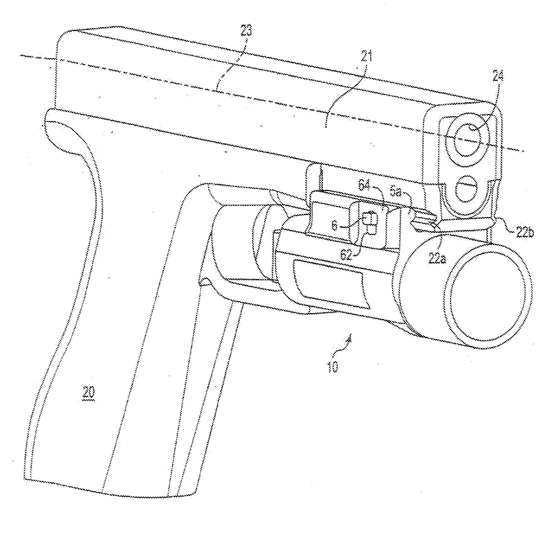
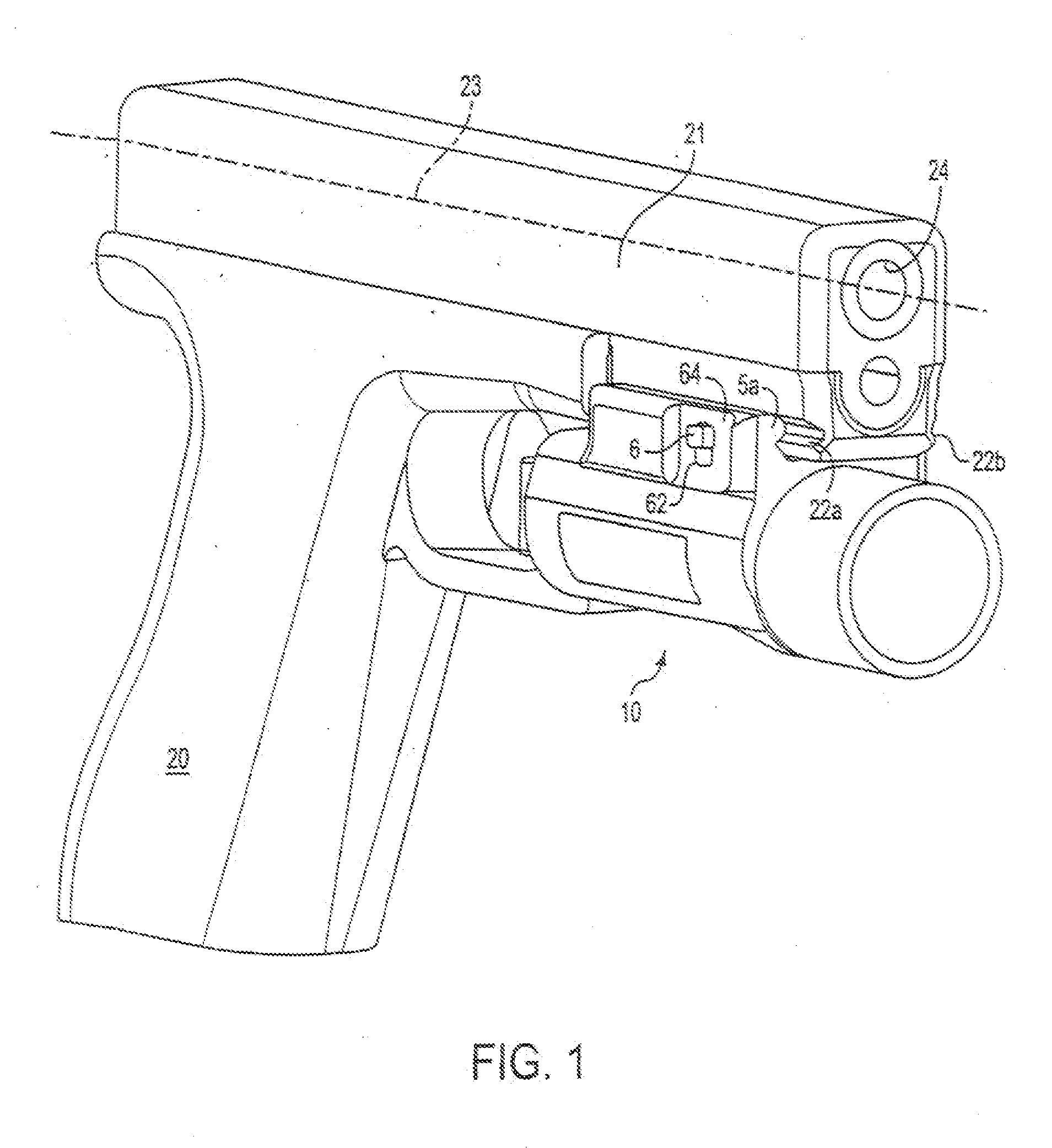
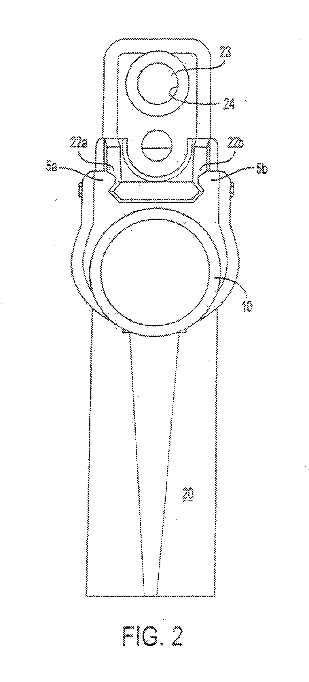