Device for mechanical weight bearing indication with load range capability

a technology of mechanical weight bearings and indicators, applied in the direction of instruments, diagnostic recording/measuring, force/torque/work measurement apparatus, etc., can solve the problems of not applying any weight, causing further damage or pain, and almost as detrimental, so as to achieve simple design, less attention, and rugged construction

Inactive Publication Date: 2008-02-21
RENESSELAER POLYTECHNIC INST
View PDF13 Cites 21 Cited by
  • Summary
  • Abstract
  • Description
  • Claims
  • Application Information

AI Technical Summary

Benefits of technology

The present invention is a mechanical load bearing indicator that can be used in various fields such as athletics, physical therapy, and gait analysis. It consists of a base plate, a load plate, and at least two snap domes that generate signals when the load plate receives more than two different loads. The invention is designed to be simple, durable, and economical to manufacture. Its unique design features a perceptible feedback signal that is only visible to the patient, minimizing the attention drawn to the patient's condition. Overall, the invention provides a convenient and effective tool for monitoring and controlling load bearing in various applications.

Problems solved by technology

The technical problem addressed in this patent is the need for a simple mechanical device that can provide unmistakable feedback signals to a patient when two different loads are being applied to their foot, so that the patient can be taught to exert a minimum desirable load on the foot during each step, but to avoid exerting more than a maximum desirable load.

Method used


Image

  • Device for mechanical weight bearing indication with load range capability
  • Device for mechanical weight bearing indication with load range capability
  • Device for mechanical weight bearing indication with load range capability

Examples


third embodiment

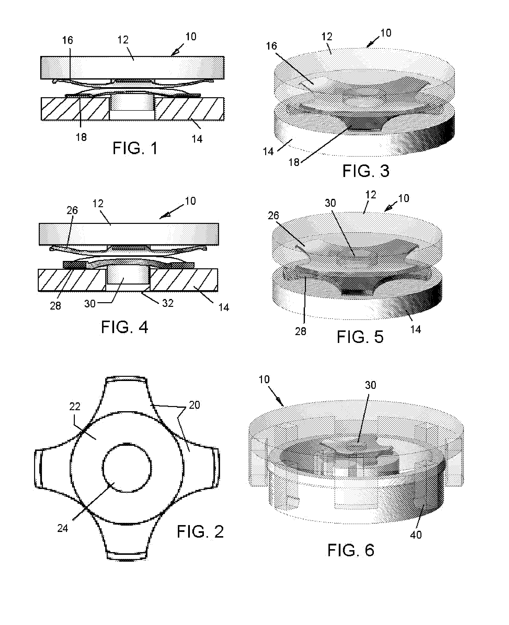
[0060]the invention is illustrated in FIG. 6.

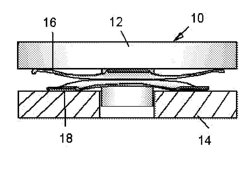
[0061]It is noted that in a preferred form of the invention as shown in all of FIGS. 1, 3, 4, 5 and 6, the load transfer plate 12 has a center post 30 to retain the lateral positions of both dome stacks. All snap domes in these embodiments will have the central hole 24 (see FIG. 2). This post 30 rides in a hole 32 provided in the base plate 14 as the plates are force toward each other during each step the user takes. The load transfer plate 12 will also be covered with a low-durometer foam or polymeric gel material, if needed.

[0062]Assembly of all the components is facilitated by a snap fit between the load transfer plate 12 which, as shown in FIG. 6 has multiple, e.g. four, retaining legs 40 that are evenly spaced around the plate 12 and embrace the base plate 14. Four support tabs guide the load transfer plate.

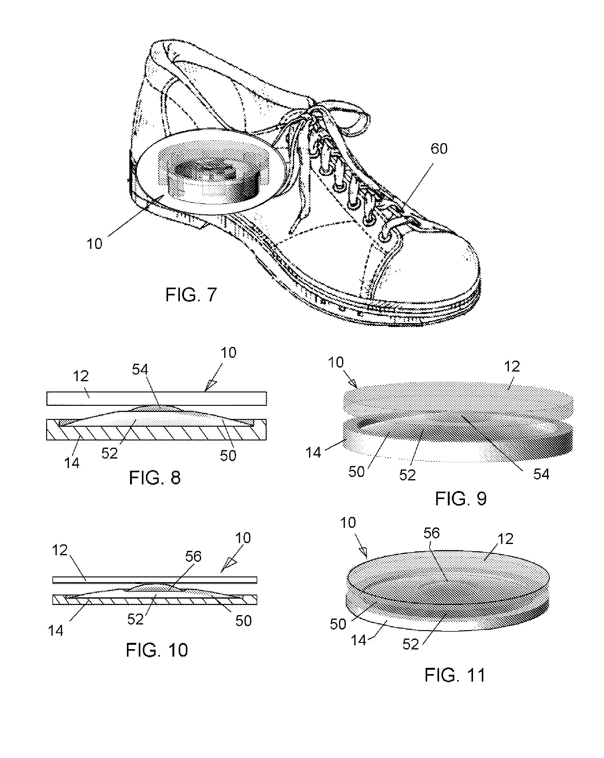
[0063]FIG. 7 shows the embodiment of FIG. 6 installed in the heel of a shoe 60 but it will be understood that any embodiment of ...


PUM


Abstract

A mechanical load bearing indicator producing signals to a user when the user applies more than selected amounts of load between an extremity of the use and a surface. The indicator has a base plate adapted to establish a frame of reference with the surface, a load plate mounted for movement toward and away from the base plate and adapted to receive loads from the user's extremity, and at least two snap domes mechanically engaged between the base plate and the load plate for generating two signals when more than two different respective loads are applied to the load plate by the extremity. The domes are either in series between the plates or are together in a dual dome containing both, or are one or more stacks of domes which individually collapse under incremental loads which are added together to form the selected lower and higher loads.

Description


Claims


Application Information

Patent Timeline
Owner RENESSELAER POLYTECHNIC INST
Why Eureka
Try Eureka