
Controller having reduced control key set and method for operating same in a learning, macro, or cloning mode

a control key and cloning mode technology, applied in the field of control key set reduction, can solve the problems of user's significant effort and attention to operating, and achieve the effect of effective toggle and high brightness

Inactive Publication Date: 2005-12-08
RB CONTROLS CO
View PDF6 Cites 42 Cited by
  • Summary
  • Abstract
  • Description
  • Claims
  • Application Information

AI Technical Summary

Benefits of technology

"The invention is a wall-mountable, configurable controller with a small number of control keys that can be dedicated to different functions. The controller has markings on its surface indicating the function of each key, making it easy for users to quickly find and operate the desired control. The controller can be used with interchangeable, removably mountable control key inserts, allowing for easy swapping of different inserts without needing to reconfigure the controller. The key inserts can have different keys for different functions, and the controller can emulate different remote control devices without including any extraneous control keys. The controller's circuitry includes a limit switch that can be pushed into a learning state to allow for easy configuration."

Problems solved by technology

Typically, controllers have a large number of control keys (which are often quite small) and thus require that the user devote significant effort and attention to operating them.
However, a user must devote significant effort and attention to operating a conventional configurable controller of the type having a large number of keys from which the user must select.
However, a user must also devote significant effort and attention to operating conventional, wall-mounted, configurable controllers that have a small number of control keys.

Method used


Image

  • Controller having reduced control key set and method for operating same in a learning, macro, or cloning mode
  • Controller having reduced control key set and method for operating same in a learning, macro, or cloning mode
  • Controller having reduced control key set and method for operating same in a learning, macro, or cloning mode

Examples


Embodiment Construction

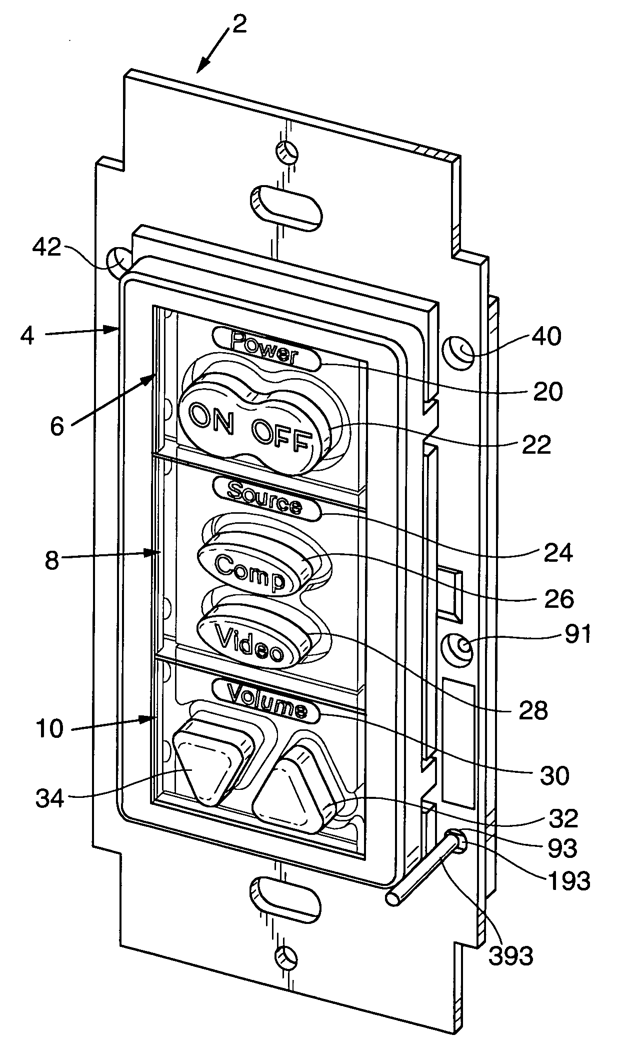
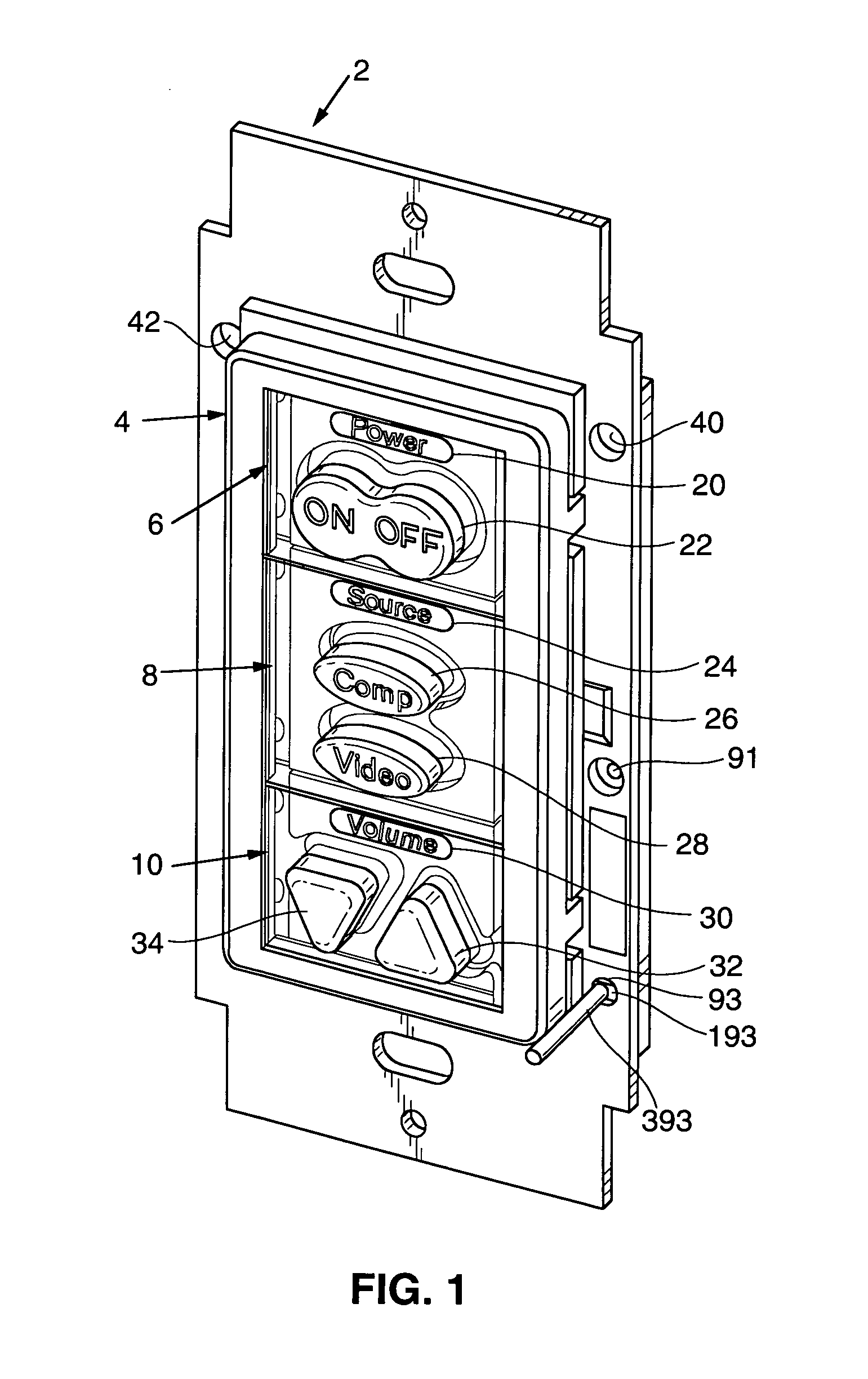
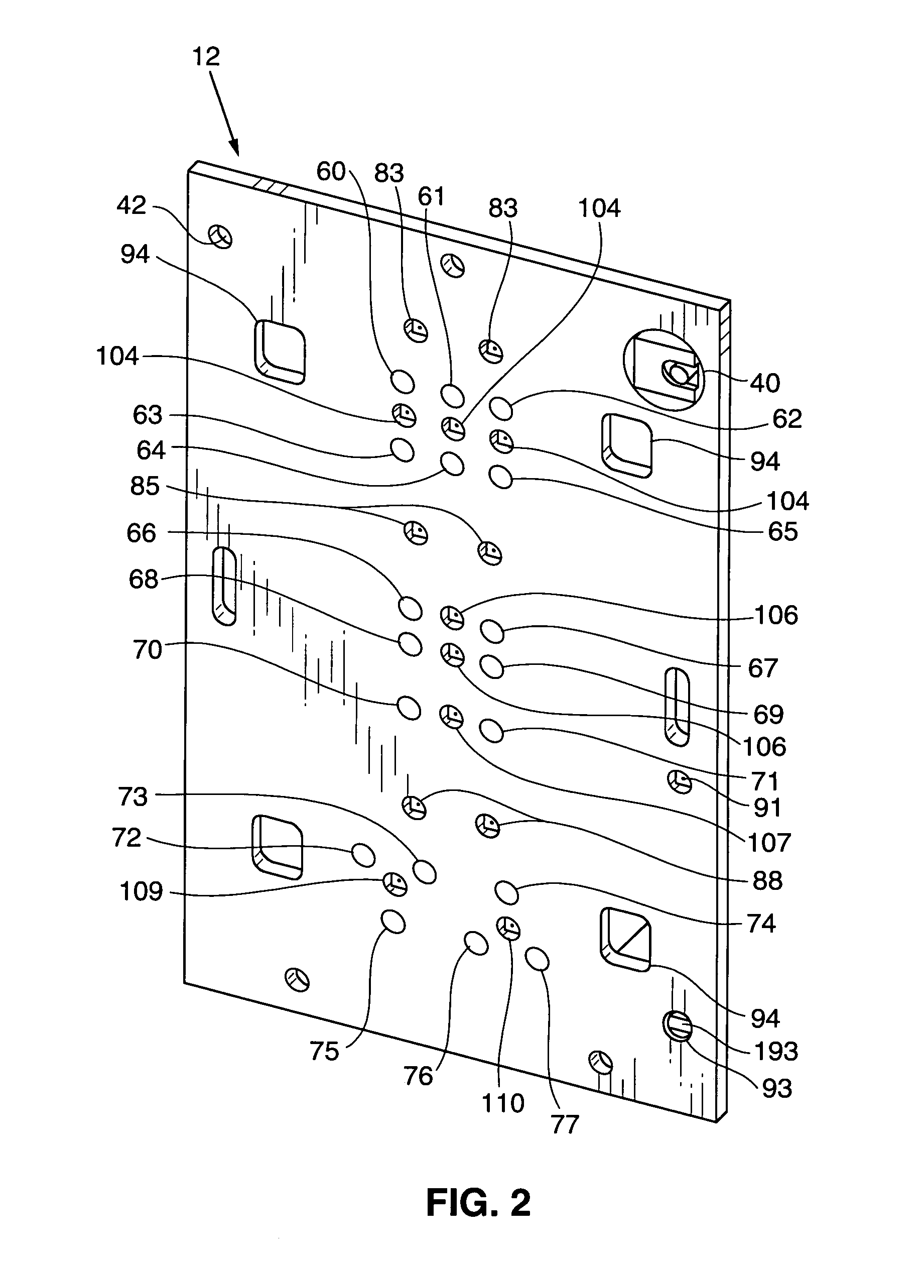
[0032] A wall-mountable embodiment of the inventive controller will be described with reference to FIGS. 1-8. As shown in FIGS. 1 and 3, this controller includes metal back plate 2 which is configured to be mounted by screws (not shown) in an electrical box in a wall. Printed circuit board (“PCB”) 12 is mounted to the back side of plate 2 with insulation plate 14 (shown in FIG. 8 but not visible in FIGS. 1 and 3) positioned between PCB 12 and back plate 2 to electrically insulate PCB 12 from plate 2. Circuit elements (to be described below) of the controller are surface mounted to PCB 12. These circuit elements include configurable microprocessor 80, crystal oscillator 81 (or another clock signal generation element) for use in generating a clock signal for use by microprocessor 80, EEPROM 82 (or another memory) for use by microprocessor 80 for storage of data which can configured, learned, cloned, and / or preloaded, illumination elements 83-91 (controlled by microprocessor 80), press...


PUM


Abstract

In some embodiments, a wall-mountable, configurable controller having control keys (e.g., less than eight keys or another small number of keys), a subassembly including circuitry, and a control key insert removably mountable to the subassembly and including at least one of the control keys. The circuitry can include a limit switch that is biased in a default state but moveable into a learning state in response to user-exerted force. In some embodiments, the controller includes an IR emitter and an IR receiver and is operable to clone another device by sending configuring radiation from the emitter to the other device's IR receiver. Preferably, the emitter and receiver are positioned so that a controller's IR emitter aligns with the IR receiver of an identical controller when the controllers are positioned face to face. In some embodiments, the controller provides audible and visual feedback to users when operating in a learning mode.

Description

CROSS-REFERENCE TO RELATED APPLICATION [0001] This application is a continuation in part of U.S. patent application Ser. No. 10 / 859,851, entitled PROGRAMMABLE CONTROLLER HAVING REDUCED CONTROL KEY SET, filed on Jun. 3, 2004.FIELD OF THE INVENTION [0002] The invention pertains to a configurable apparatus for controlling a projector or other device (e.g., an audio, video, or audiovisual device) and to methods for operating such an apparatus in a learning and / or cloning mode. In some embodiments, the invention is a wall-mountable projector controller having a first key set, a second key set, a third key set and configurable switches actuatable by pressing control keys in the key sets. Each key set includes at least one control key (or zero or at least one control key) but no more than a small number of control keys, and the key sets are in distinct regions of the controller's surface. Each configurable switch actuatable by pressing a key of the first key set is configured only to perfo...

Claims


Application Information

Patent Timeline
Patent Type & Authority Applications(United States)
IPC IPC(8): H01H1/00H01H13/70
CPCH01H13/70H01H2300/042H01H2217/026H01H2219/039H01H2221/012H01H2221/018H01H2223/034H01H2223/058H01H2229/022H01H2229/034H01H2229/042H01H2233/042H01H2239/048H01H2239/066H01H2300/04H01H2207/048
Inventor BROWN, PAUL ANSONTHIEME, AARON DANIEL
Owner RB CONTROLS CO
Learn More