Lens driving device, autofocus camera, and camera-equipped mobile terminal

a technology of driving device and camera, which is applied in the direction of camera focusing arrangement, printer, instruments, etc., can solve the problems of labor, inability to use, and inability to draw out wires from the coil,

Inactive Publication Date: 2012-04-19
SHICOH ENG
View PDF2 Cites 39 Cited by
  • Summary
  • Abstract
  • Description
  • Claims
  • Application Information

AI Technical Summary

Benefits of technology

[0022]According to the third aspect of the invention, it is possible to provide a camera-equipped mobile terminal that exerts the functional effects of the second aspect of the invention.

Problems solved by technology

However, in a case of providing two second coils to the lens support and passing current through each of the second coils, the other side (rear side) spring member, which is already being used for the first coil as a current path to the second coil, cannot be used.
However, since the one end and the other end of the coil wire of the second coil are drawn out from the lens driving device to be connected to the external power terminal or a control unit, labor is required for drawing out each wire and for connection to the external power terminal or control unit, and there is concern over the wires drawn out from the coil becoming a hindrance and restricting the driving of the lens support.

Method used


Image

  • Lens driving device, autofocus camera, and camera-equipped mobile terminal
  • Lens driving device, autofocus camera, and camera-equipped mobile terminal
  • Lens driving device, autofocus camera, and camera-equipped mobile terminal

Examples


Embodiment Construction

[0030]Below, an embodiment of the present invention will be explained in detail referring to the attached drawings. A lens driving device 1 according to the present embodiment shown in FIG. 6 is a lens driving device of an autofocus camera built into a mobile phone.

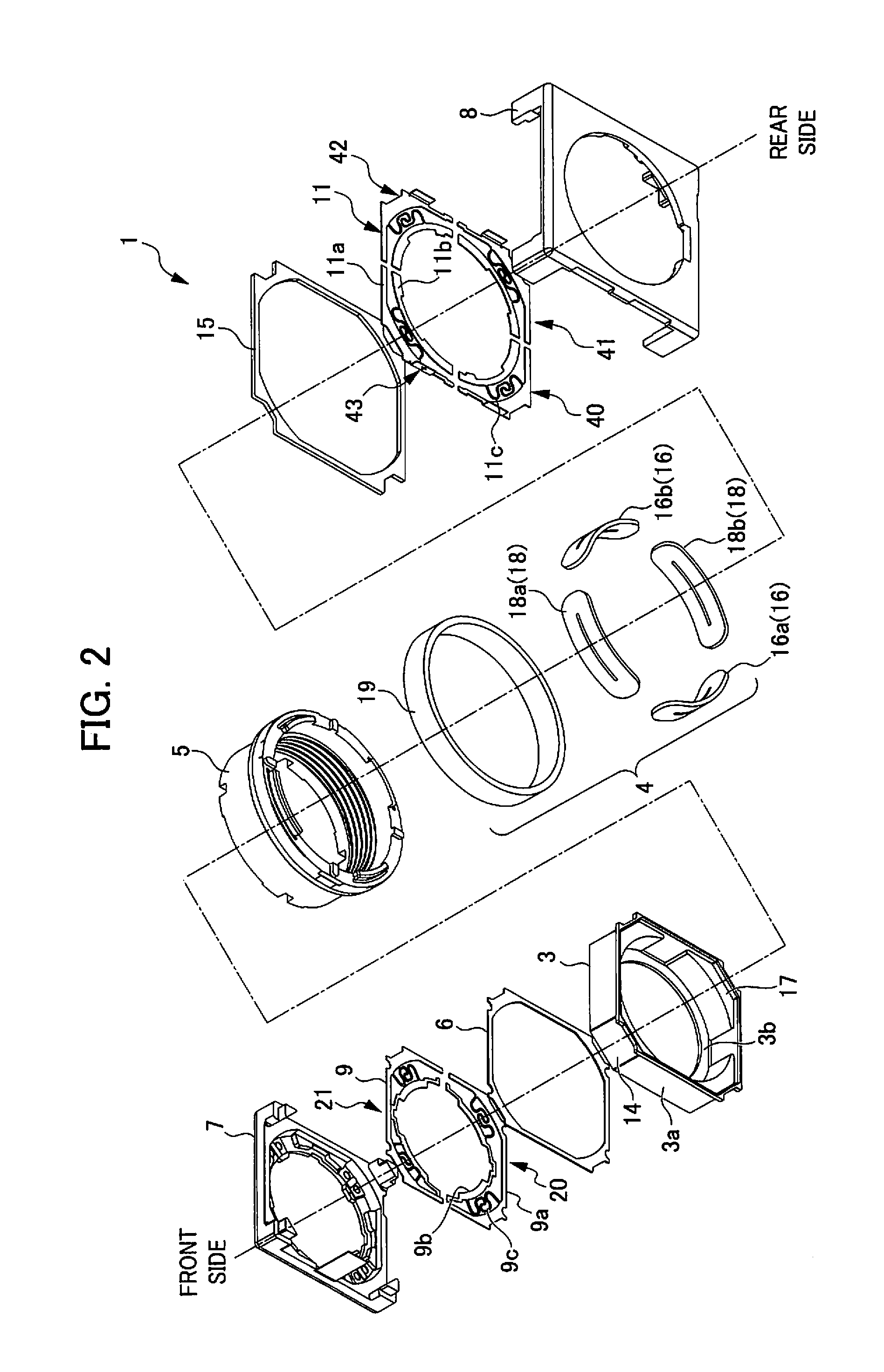
[0031]As shown in FIGS. 2 and 4, this lens driving device 1 is provided with a lens support 5 which supports a lens (not illustrated) at its inner circumference; a yoke 3 which arranges the lens support 5 so as to be freely moveable to its inner circumferential side; a frame 7 and front-side spring member (first spring member) 9 disposed at the optical axis direction of the yoke 3; and a base 8 and rear-side spring member (second spring member) 11 disposed at the rear side of the yoke 3, in which an insulating rear-side spacer 15 is disposed between the rear-side spring member 11 and the yoke 3. A coil 4 is fixed at the outer circumference of the lens support 5. It should be noted that an insulating front-side spacer 6 is...


PUM


Abstract

In a lens driving device of the present invention, each magnet is provide to face an outer circumferential face of a first coil, and face a second coil at a position at which the second coil is provided. A first spring member and a second spring member are configured by a plurality of six springs separated from each other, each coil wire end of the first coil and the two of the second coils being connected to a different spring, respectively, and when moving a lens support (5) in the optical axis direction, electric current is flowed through the first coil, and when moving the lens support in an X-Y direction that is orthogonal to the optical axis, a predetermined electric current is flowed through a predetermined one of the second coils.

Description

[0001]This application is based on and claims the benefit of priority from Japanese Patent Application No. 2010-234282, filed on 19 Oct. 2010, the content of which is incorporated herein by reference.BACKGROUND OF THE INVENTION[0002]1. Field of the Invention[0003]The present invention relates to a lens driving device, an autofocus camera and a camera-equipped mobile terminal.[0004]2. Related Art[0005]Prior Art Document 1 (Japanese Unexamined Patent Application, Publication No. 2009-80217) discloses providing a first coil wound around a circumferential direction of a lens support, a magnet provided at a fixed member and disposed to face the first coil, a first spring member provided on one side (front side) of the lens support in an optical axis direction, and a second spring member provided on the other side (rear side) of the lens support in the optical axis direction, and moving the lens support in the optical axis direction by passing current through the first coil.[0006]In the t...

Claims


Application Information

Patent Timeline
Patent Type & Authority Applications(United States)
IPC IPC(8): G02B27/64G02B7/09H04N5/232
CPCG02B27/646G03B3/10G03B5/00G02B7/08G03B2205/0069H02K41/0354H02K2201/18G03B2205/0015
Inventor SHIRAKI, MANABUTOYAMA, KOJI
Owner SHICOH ENG
Why Eureka
Try Eureka